Signal assessment

a technology of signal assessment and transmission, applied in the field of communication system, can solve the problems of substantial network load, inability to distinguish between subsequent transmission frames, and insufficient information in the received data frame to uniquely identify the transmission, etc., and achieve the effect of reducing network load

Inactive Publication Date: 2005-06-23
INTEL CORP
View PDF7 Cites 97 Cited by
  • Summary
  • Abstract
  • Description
  • Claims
  • Application Information

AI Technical Summary

Benefits of technology

[0012] It is in this respect another particular object of the invention to provide such apparatus and method that reduce network load when performing performance measurement.
[0033] One advantage according to the invention is that it allows precise comparisons of received signal strength or other reception characteristics for an individual frame transmission or message between all access points who received a given message, without unnecessarily increasing network load.

Problems solved by technology

One of the issues in using RSSI information as a basis for network management is to be able to link the RSSI information with a particular station.
However, this in itself is not enough since a station may send different frames at different power levels depending on the situation, and movement of a station may also cause different frames to be received with different power levels.
Also, transmission errors such as collisions may mean that one AP may successfully receive a transmission while another AP does not.
A primary drawback with the proposed solution is that, in itself, the received data frame does not necessarily contain sufficient information to uniquely identify the transmission.
However, if more than a single retransmission of the frame is performed it is no longer possible to distinguish between subsequent transmitted frames.
A secondary drawback with the proposed solution is that the amount of data transmitted over the network between the access points and the access router is multiplied by the number of access points, receiving the transmitted frame or message, which generates a substantial network load.

Method used


Image

  • Signal assessment
  • Signal assessment
  • Signal assessment

Examples


Embodiment Construction

[0039] In the following description, for purposes of explanation and not limitation, specific details are set forth, such as particular techniques and applications in order to provide a thorough understanding of the present invention. However, it will be apparent to one skilled in the art that the present invention may be practiced in other embodiments that depart from these specific details. In other instances, detailed descriptions of well-known methods and apparatuses are omitted so as not to obscure the description of the present invention with unnecessary details.

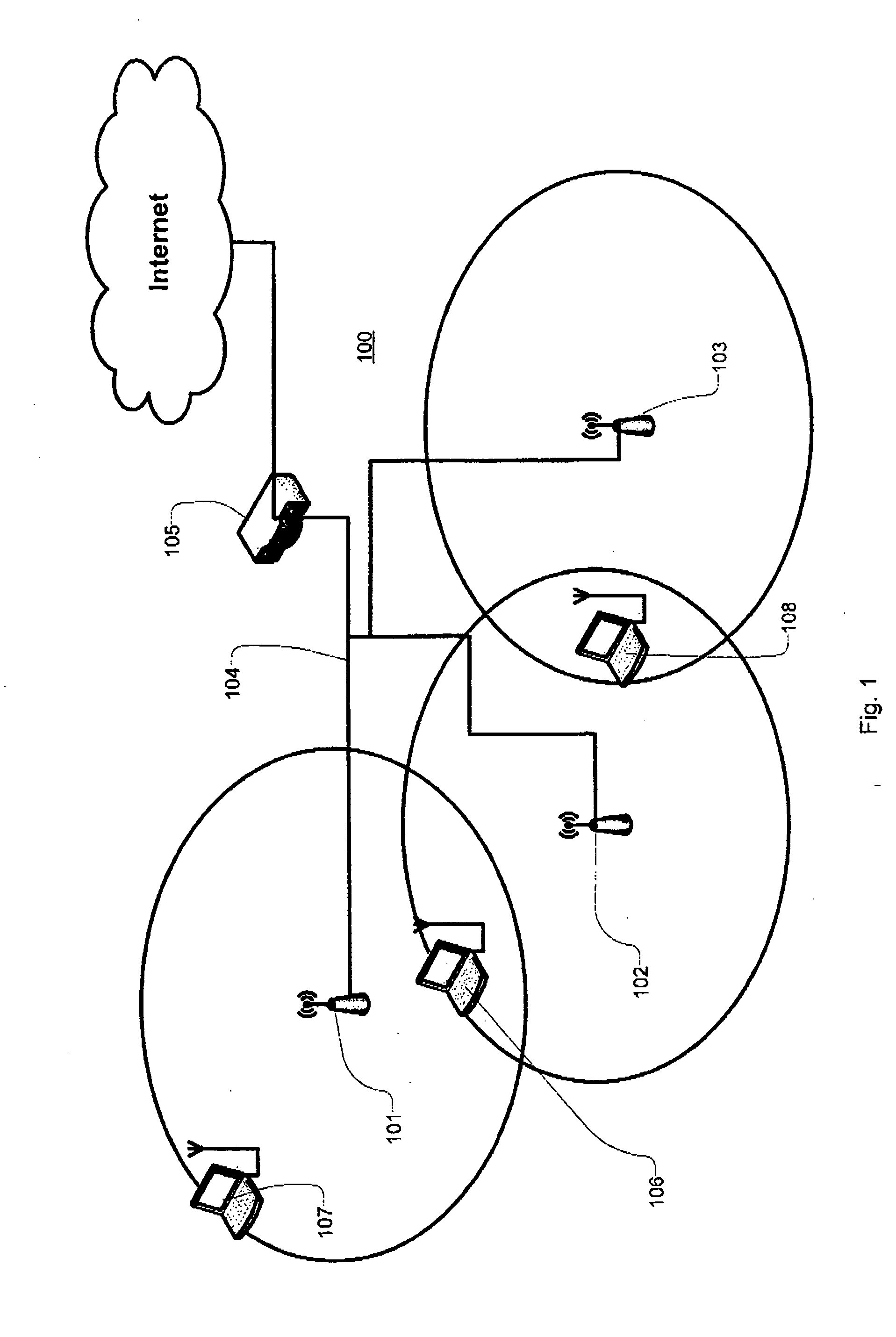
[0040] A simplified illustrative embodiment of the invention is shown in FIG. 1 and comprises a LWAP system (Light weight access point), and consists of first 101, second 102 and third 103 access points, according to the third aspect of the invention connected via a wired network 104 to an access router 105 according to the fourth aspect of the invention. Three wireless stations are communicating via the network: a fi...


PUM


Abstract

A communication system comprises at least a first and a second access point and a network arrangement device to receive radio signaling from at least a first station and to relay messages received through the radio signaling from the at least first station to the network management device. Each of the access points extracts performance data, for each message received from the at least first station, from the radio signaling. Each of the access points generates a message identity for each message received from the station. The message identity uniquely identifies a transmitted message, each of the at least first and second access point is provided to send radio performance messages to the network management device comprising at least the message identity and the performance data, and the network management device is provided to receive the radio performance messages from the at least first and second access point.

Description

TECHNICAL FIELD OF THE INVENTION [0001] The present invention relates to a communication system, an access point and an access router for communication in a network and a method therefore. More specifically the present invention relates to a communication system, an access point and an access router for increasing performance in a network comprising radio links and a method therefore. BACKGROUND OF THE INVENTION [0002] There is growing interest in the idea of light-weight access points, where a wireless LAN (Local Area Network) consists of a number of cheap and simple base station devices, also known as access points or APs connected to a central access router or AR. The AR is responsible for forwarding of data received by the APs to the wider network, and can also perform network management functions. Evidence of the level of interest is the formation of an IETF (Internet Engineering Task Force) study group who are producing a draft for LWAPP (light-weight access point protocol). [...

Claims


Application Information

Patent Timeline
Patent Type & Authority Applications(United States)
IPC IPC(8): H04L12/28H04W36/12
CPCH04W36/0005
Inventor LEWIS, MICHAEL
Owner INTEL CORP
Why Eureka
Try Eureka