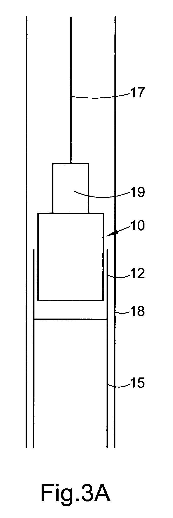
[0015] Preferably, the downhole tool is adapted to be located and suspended in a borehole on a
wireline or slickline. As is well known in the art,
wireline\slickline offers advantages in the speed of tool deployment and
recovery. Where it is desired to exert an upwardly directed force on the activating member, it may be preferred to deploy the tool on
wireline\slickline, as this is suitable for exerting an upwardly directed force, and allows relatively quick deployment\
recovery of the tool compared to other methods. Alternatively, the downhole tool may be adapted to be located and suspended in a borehole on
coiled tubing or the like.
Coiled tubing also offers advantages in speed of tool deployment and
recovery when compared to conventional sectional tubing, and where it is desired to exert a downwardly directed force on the activating member it may be preferred to deploy the tool on
coiled tubing.
[0016] Preferably also, the activating member is adapted to be translated in an upward direction corresponding to said one axial direction to thereby translate the driven member in a downward direction corresponding to said opposite axial direction. Thus the activating member may be adapted to be translated on
exertion of a pulling force on the activating member, to generate a pushing force on the driven member. The tool may thus have a particular utility for releasing a downhole lock of the type which is released by a downward movement, as the tool allows this action to be achieved through an upward jarring, with the advantages discussed above. Alternatively, the activating member may be adapted to be translated in a downward direction corresponding said one axial direction, to thereby translate the driven member in an upward direction corresponding to said opposite axial direction. Thus the activating member may be adapted to be translated on
exertion of a pushing force on the activating member, to generate a pulling force on the driven member.
[0017] The activating member may be movable in a first direction corresponding to said one axial direction and a second direction corresponding to said opposite axial direction, to cause a corresponding movement of the driven member in the second and the first axial directions, respectively. Alternatively, the activating member may be operatively associated with the driven member such that on translation of the activating member in said one axial direction, the driven member is translated in the opposite direction, and on translation of the activating member in said opposite direction, the driven member remains axially stationary. Thus repeated movements of the activating member in said one axial direction and then said opposite axial direction may facilitate successive translations of the driven member in said opposite direction, to progressively translate the driven member to a desired position. The tool may thus be arranged to selectively translate the driven member in response to translation of the activating member only in a selected axial direction. The tool may further comprise a mechanism for allowing selective translation of the driven member.
[0021] The rotary member may take the form of a threaded member such as a threaded shaft or screw, translation of the activating member rotating the threaded member about an axis thereof, which axis may be substantially parallel to axes of one or both of the activating and driven members. The threaded member may comprise first and second sets of threads or threaded portions of opposite hand (rotational orientation), one of the first and second threads associated with the activating member and the other with the driven member. This may facilitate translation of the driven member in an opposite direction to the activating member when the rotary member is rotated by the activating member.
[0025] The tool may further comprise at least one, preferably a plurality of drive transfer members for transferring drive between the activating member and the driven member. Where the tool comprises a rotary member, the tool may further comprise at least one drive transfer member for transferring drive between the activating member and the rotary member, and at least one drive transfer member for transferring drive between the rotary member and the driven member. The drive transfer member may take the form of a ball, pin, key, tooth, dog, follower or the like. The drive transfer member may be fixed relative to the activating member and\or the driven member for movement therewith. Thus movement of the drive transfer member independently of the respective activating\driven member may be prevented.

