Self-sustaining center-anchor microelectromechanical switch and method of manufacturing the same

a microelectromechanical switch and center-anchor technology, applied in the direction of electrical apparatus, electrostrictive/piezoelectric relays, waveguide devices, etc., can solve the problems of reducing the stability and reliability of the switch, reducing the reliability, and reducing the reliability, so as to improve the stability of the membrane stiction problem, the effect of less sensitive to thermal deformation and stable operation

Inactive Publication Date: 2005-06-30
INTELLECTUAL DISCOVERY CO LTD
View PDF9 Cites 8 Cited by
  • Summary
  • Abstract
  • Description
  • Claims
  • Application Information

AI Technical Summary

Benefits of technology

[0019] Further, the present invention is directed to a microelectromechanical switch that is inserted with a self-sustaining center-anchor to suppress deformation of a movement plane generated during manufacturing and operation process, and to improve the ground line contact phenomenon of an upper electrode, leading to the improvement of reliability, and to improve a signal isolation feature while maintaining an existing feature of insertion loss since a signal line gap is much larger than that of the microelectromechanical switch.
[0021] Further, the present invention is directed to a microelectromechanical switch less sensitive to thermal deformation generated during manufacturing and operation process, and having an improved membrane stiction problem to perform a stable operation, and the signal isolation feature is excellent since a signal line gap is relatively large, leading to high yield in manufacturing.

Problems solved by technology

In order to control a signal in an electronic system with a high frequency bandwidth, an easily integratable semiconductor switch, such as a field effect transistor (FET) or a p-I-n diode, has been used, but since each semiconductor has problems, such as a high insertion loss, a low isolation loss, and a signal distortion, a research on the microelectromechanical switch has widely been progressed.
This contact degradation increases a contact resistance of the signal line 3 and causes a signal delivery to be unstable, thus reducing the reliability.
Therefore, when the surface of the upper electrode 46 made of a metal during manufacturing process or operation process is deformed by thermal expansion, a problem occurs that the movement plane does not completely contact with the signal line so as to permanently remain open, and stiction occurs between the upper electrode 46 and the lower electrode 42 sustained in a narrow gap, thus reducing the stability and reliability of the switch.
A drawback of this membrane type microelectromechanical switch is the deformation of a membrane and the stiction problem.
Consequently, owing to the deformation of the movement plate, problems occur that a normal switching operation cannot be performed when the movement plane becomes abnormally apart from the substrate or is tilted toward one side, and when the movement plane is collapsed near the substrate, that the contact portion of the movement plane permanently contacts with the signal line.
Further, the gap between both electrodes for generating the electrostatic force maintains as close as several micrometers, so that the stiction problem that the driving element adheres to other fixing elements is easy to generate, which acts as significant drawbacks in the operation and reliability of the switch.
As illustrated above, since the conventional microelectromechanical switch is configured in the cantilever type or the membrane type, it has structural problems, such as the thermal deformation and stiction.
Such problems have a significant influence on the reliability and the signal isolation feature of the microelectromechanical switch used for improving high insertion loss, low signal isolation, signal distortion, etc.

Method used


Image

  • Self-sustaining center-anchor microelectromechanical switch and method of manufacturing the same
  • Self-sustaining center-anchor microelectromechanical switch and method of manufacturing the same
  • Self-sustaining center-anchor microelectromechanical switch and method of manufacturing the same

Examples


Embodiment Construction

[0033] The present invention will now be described more fully hereinafter with reference to the accompanying drawings.

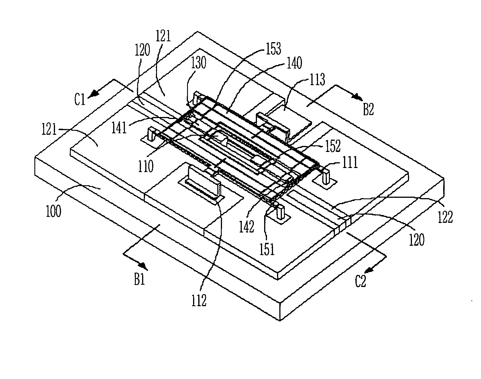
[0034]FIG. 4 is a perspective view of a self-sustaining center-anchor microelectromechanical switch according to a preferred embodiment of the present invention, and FIGS. 5, 6A and 6B are a plan view and cross-sectional views taken along line B1-B2 and line C1-C2 of FIG. 4, respectively.

[0035] Referring to FIG. 4, an input portion of transmission line 120 and an output portion of transmission line 120 are formed on a semiconductor substrate or a dielectric substrate 100, at a predetermined gap, and an insulating material 122 is formed at both sides of the transmission lines 120 to fabricate parallel dielectric-moving plates 130, and ground lines 121 are formed at both sides of the insulating material 122.

[0036] The input portion and the output portion transmission line 120 are spaced apart with a constant distance with a self-sustaining center-anchor 110 therebet...


PUM


Abstract

Provided is a self-sustaining center-anchor microelectromechanical switch driven by an electrostatic force used for controlling a signal transmission in an electronic system, which can suppress deformation of a movement plane generated during manufacturing and operation process by inserting the self-sustaining center-anchor, and improve a ground line contact phenomenon of an upper electrode, thereby enhancing reliability and signal isolation feature while maintaining an existing insertion loss feature compared to the microelectromechanical switch of the prior art.

Description

BACKGROUND [0001] 1. Field of the Invention [0002] The present invention relates to a self-sustaining center-anchor microelectromechanical switch and a method of manufacturing the same and, more particularly, to a self-sustaining center-anchor microelectromechanical switch that driven by an electrostatic force used for controlling a RF signal in an electronic system for high frequency. [0003] 2. Discussion of Related Art [0004] In order to control a signal in an electronic system with a high frequency bandwidth, an easily integratable semiconductor switch, such as a field effect transistor (FET) or a p-I-n diode, has been used, but since each semiconductor has problems, such as a high insertion loss, a low isolation loss, and a signal distortion, a research on the microelectromechanical switch has widely been progressed. [0005] Generally, the microelectromechanical switch comprises a movement element that moves relative to a substrate, and a driving element that drives the movement ...

Claims


Application Information

Patent Timeline
Patent Type & Authority Applications(United States)
IPC IPC(8): H01H51/22H01H59/00H01P1/12
CPCH01P1/127H01H59/0009H01H59/00
Inventor LEE, JAE WOOKANG, SUNG WEONKIM, YOUN TAE
Owner INTELLECTUAL DISCOVERY CO LTD
Why Eureka
Try Eureka