

Exposure apparatus and method
a technology applied in the field of exposure apparatus and method, can solve the problems of lowering transfer accuracy and yield, and cannot meet the demand for high-quality exposure, and achieve the effect of high-quality exposur
- Summary
- Abstract
- Description
- Claims
- Application Information
AI Technical Summary
Benefits of technology
Problems solved by technology
Method used
Image

Examples
first embodiment
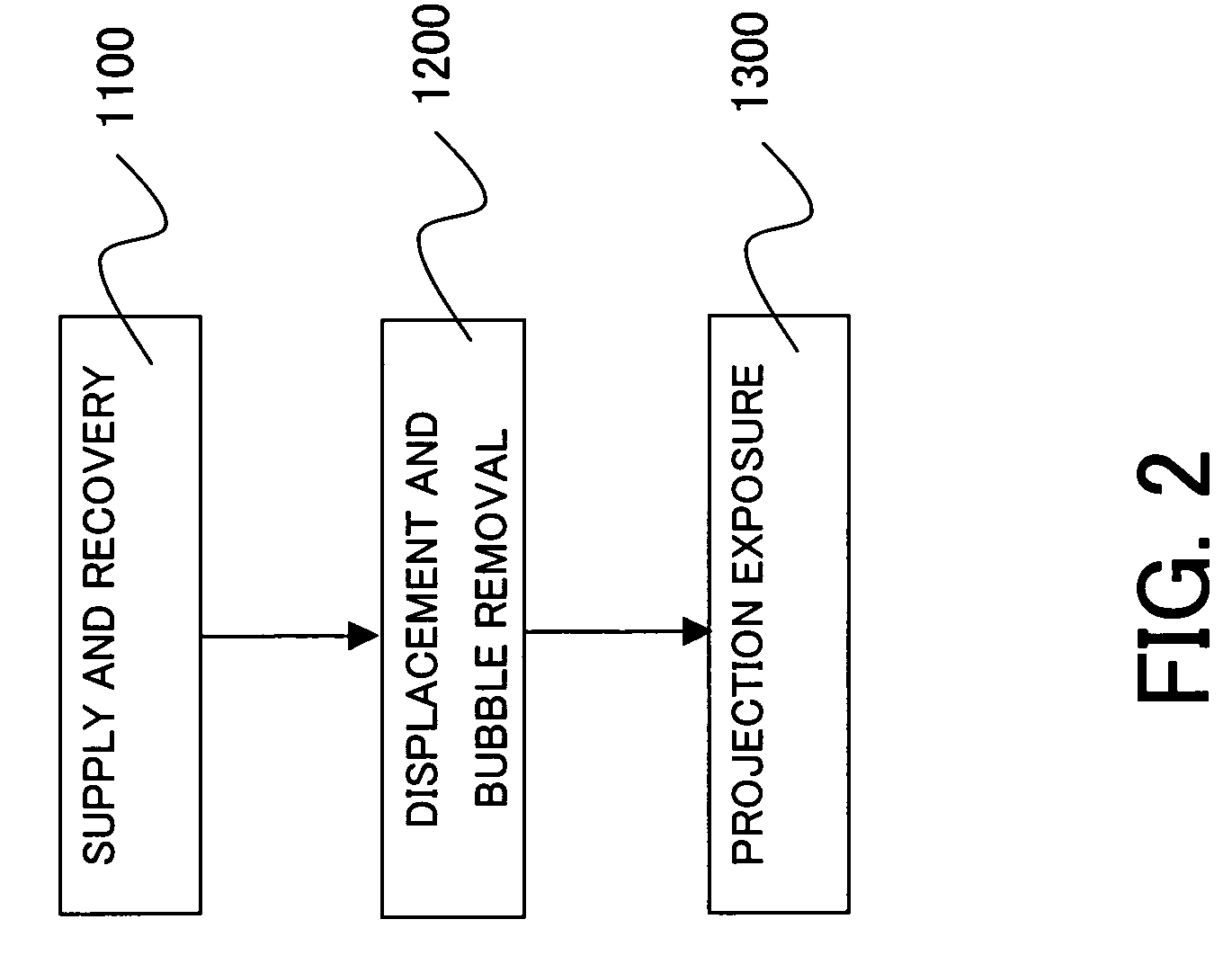
[0042] Referring now to FIGS. 3 and 4, a description will be given of steps 1100 and 1200 of a first embodiment. Here, FIGS. 3 and 4 are schematic enlarged sectional view near the wafer 170 and the final optical element 144 in the projection optical system 140 closest to the wafer 170 in the steps 1100 and 1200 of the first embodiment. Suppose that the fluid 181 is filled between the surface 171 of the wafer 170 and the bottom surface 145 of the final optical element 144 in the initial state. The supply / recover mechanism 180 of this embodiment includes a supply nozzle 182, a recovery nozzle 184, and a displacement / bubble removal mechanism 190. While air curtains are actually formed outside the supply nozzle 182 and the recovery nozzle 184 in FIGS. 3 and 4, FIGS. 3 and 4 omits them for illustration purposes. This is true of the following description.
[0043] The supply nozzle 182 continuously or intermittently supplies the fluid 181 to the space between the bottom surface 145 of the o...
second embodiment
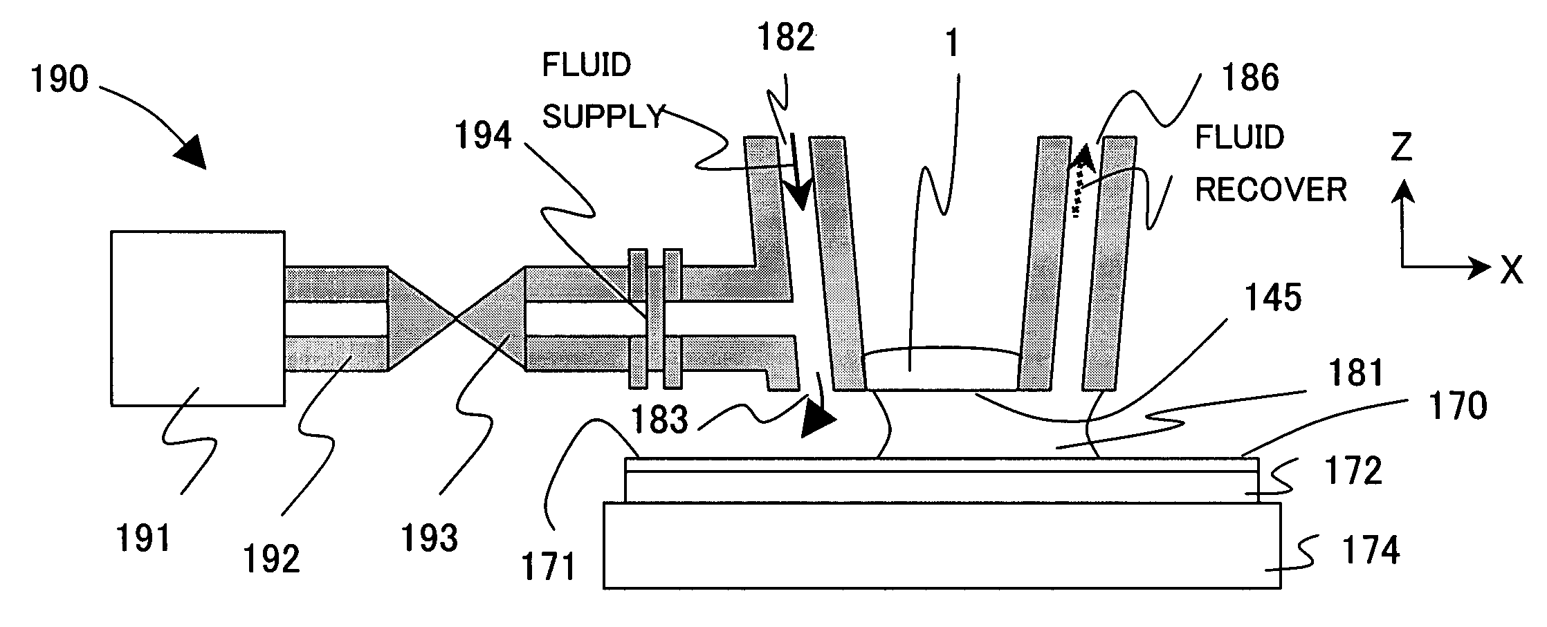
[0052] Referring now to FIG. 5, a description will be given of the steps 1100 and 1200 according to a second embodiment. Here, FIG. 5A is a schematic enlarged sectional view near the optical element 144 in the projection optical system 140 at the time of the air bubble elimination in the steps 1100 and 1200. FIG. 5B shows a state near the gas-liquid separating membrane 194 at the time of the fluid recovery. The supply / recovery mechanism 180 of this embodiment includes a supply nozzle 182A, a supply-sie valve 185, a pump-side valve 186, and a displacement / bubble elimination mechanism 190A. The displacement / bubble elimination mechanism 190A includes a pump 191, a pipe 192, a gas-liquid separating membrane 194A, a valve disc 195, and an O-ring 196. Those elements in FIG. 5, which are corresponding elements in FIGS. 3 and 4 are designated by the same reference numeral, and a duplicate description will be omitted.
[0053] The first embodiment provides dedicated nozzles for supply and reco...
third embodiment
[0061] Referring now to FIG. 6, a description will be given of the steps 1100 and 1200 according to a third embodiment. Here, FIG. 6 is a schematic enlarged sectional view near the optical element 144 in the projection optical system 140 in the steps 1100 and 1200 according to the third embodiment. Those elements in FIG. 6, which are corresponding elements in FIG. 5, are designated by the same reference numeral, and a duplicate description will be omitted. Similar to the second embodiment, this embodiment provides the valves 185 and 186 at the upstream side of the supply port 183A of the nozzle 182A, and share the nozzle 182A used to supply and recover the fluid 181. While the second embodiment provides the gas-liquid separating membrane 194 with a valve structure, this embodiment arranges a pipe 197 parallel to the gas-liquid separating membrane 194 and provides the pipe 197 with the valve 198 instead of the gas-liquid separating membrane 194.
[0062] A description will now be given...
PUM
 Abstract
Description
Claims
Application Information