Method, apparatus, and program for discriminating calcification patterns

a calcification pattern and program technology, applied in the field of methods, apparatuses, and programs for discriminating calcification patterns, can solve the problems of difficult judgment, inability to say that the diagnoses are completely objective, and burden on the diagnostician, so as to reduce the detection of pseudo and accurately detect the true calcification patterns

Inactive Publication Date: 2005-06-30
FUJIFILM HLDG CORP +1
View PDF4 Cites 2 Cited by
  • Summary
  • Abstract
  • Description
  • Claims
  • Application Information

AI Technical Summary

Benefits of technology

[0018] The present invention has been developed in view of the foregoing circumstances. It is an object of the present invention to provide a method, an apparatus, and a program for discriminating calcification patterns that enables reduction in detection of pseudo microcalcification patterns, thereby accurately detecting true calcification patterns.
[0035] Further, by observing the dispersion of pixel values of the pixels within the linear structural elements, the magnitude of contrast can be accurately judged. Thereby, the judgment accuracy, in judging whether the candidate points are pseudo microcalcification patterns, can be improved.

Problems solved by technology

However, the observation of radiation images is largely dependent on the experience and the image reading capabilities of a diagnostician, and therefore it cannot be said that the diagnoses are completely objective.
However, it is not always the case that these abnormal patterns are accurately discriminated by the diagnostician.
However, if a great number of candidates for microcalcification patterns are detected, the burden on the diagnostician becomes great, and judgment becomes difficult.

Method used


Image

  • Method, apparatus, and program for discriminating calcification patterns
  • Method, apparatus, and program for discriminating calcification patterns
  • Method, apparatus, and program for discriminating calcification patterns

Examples


Embodiment Construction

[0046] Hereinafter, an embodiment of a calcification pattern discriminating apparatus 1 that performs the calcification pattern discriminating method of the present invention will be described with reference to the attached drawings.

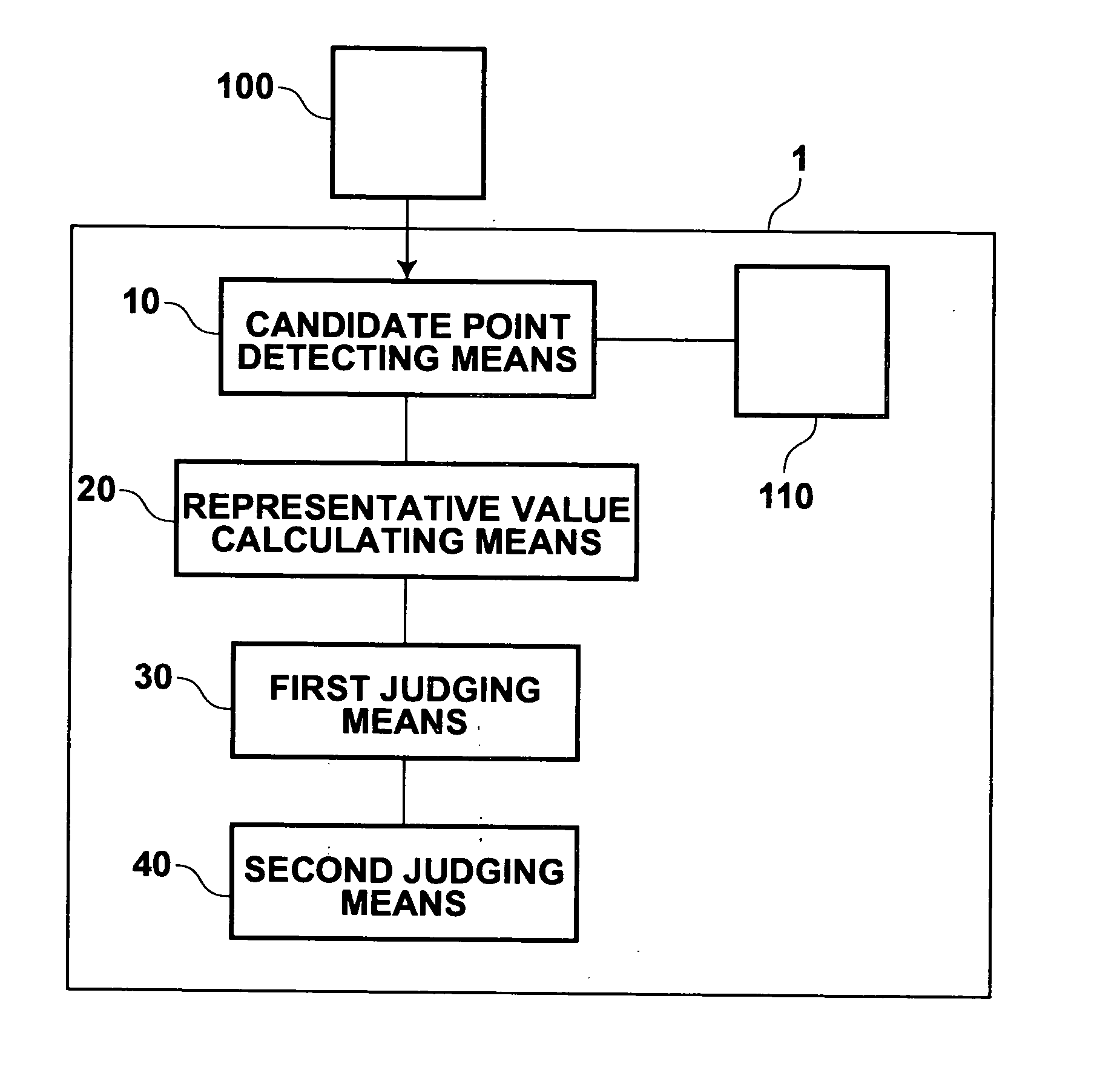
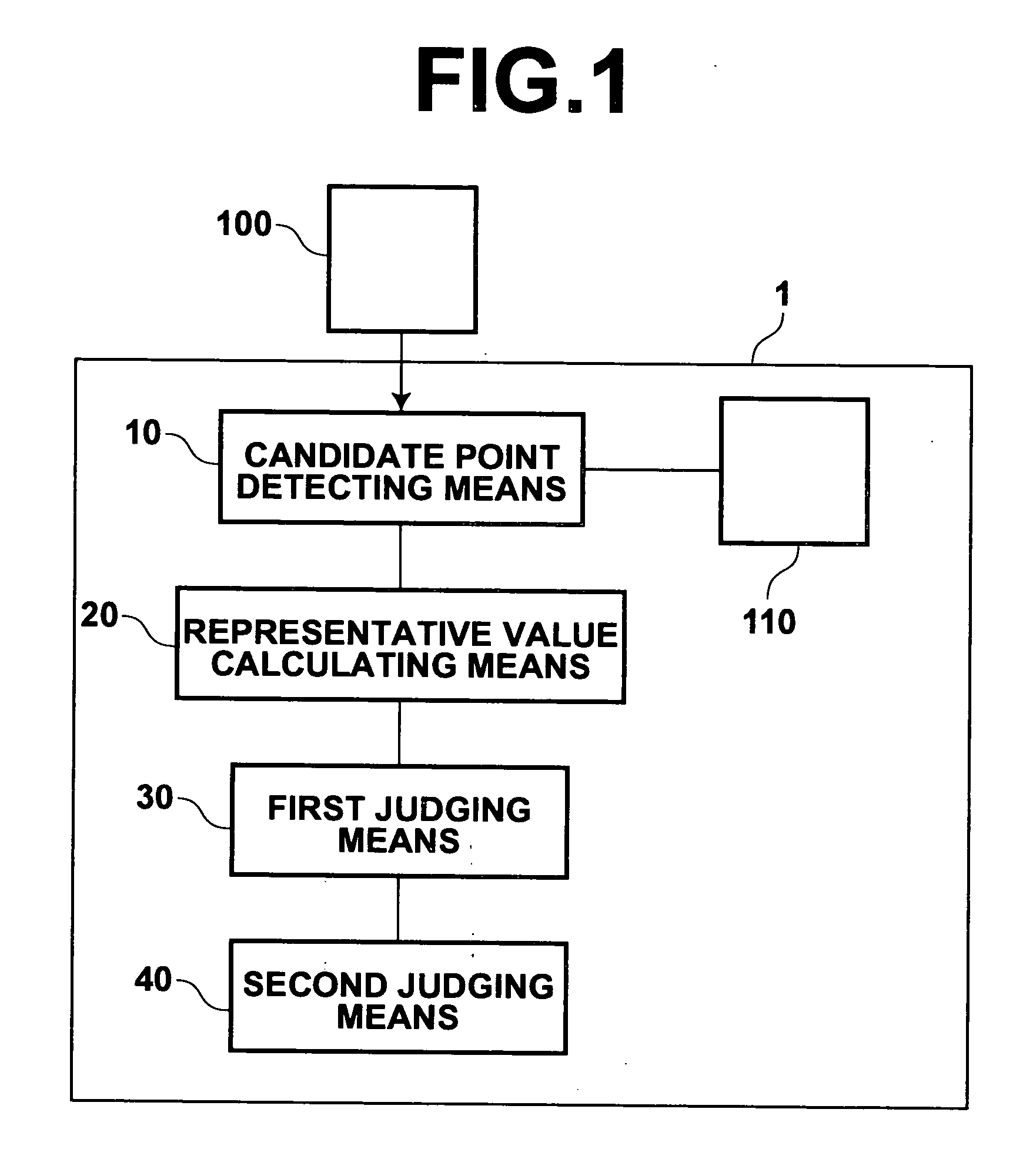
[0047] As illustrated in FIG. 1, the calcification pattern discriminating apparatus 1 comprises: a candidate point detecting means 10; a representative value calculating means 20; a first judging means 30; and a second judging means 40. The candidate point detecting means 10 detects candidate points for microcalcification patterns from an original medical image 100, in which a breast is imaged. The representative value calculating means 20 obtains representative values of pixels, which are present along a plurality of lines that pass through the detected candidate points in a plurality of directions. The first judging means 30 judges whether the candidate points are points included in linear structures, which appear along the line for which the represen...


PUM


Abstract

Detection of pseudo calcification patterns is reduced, to improve detection accuracy of microcalcification patterns. Candidate points for microcalcification patterns are detected from a medical image. Mean pixel values are obtained for pixels along a plurality of lines that pass through the candidate points in a plurality of directions. Whether the candidate points are points within linear structural elements that appear along a line, along which the mean pixel value is greatest (maximum line), is judged based on the difference between the maximum mean pixel value and the minimum mean pixel value.

Description

BACKGROUND OF THE INVENTION [0001] 1. Field of the Invention [0002] The present invention relates to a method, an apparatus, and a program for discriminating calcification patterns that appear in radiation images of subjects. [0003] 2. Description of the Related Art [0004] Conventionally, it is common practice to discover diseased portions by observing radiation images of subjects. It is also common practice to observe the diseased portions to diagnose progression of a disease and the like. However, the observation of radiation images is largely dependent on the experience and the image reading capabilities of a diagnostician, and therefore it cannot be said that the diagnoses are completely objective. [0005] For example, mammograms (diagnostic radiation images having breasts as subjects) are obtained for the purpose of screening for breast cancer. It is necessary to detect characteristic cancerous portions from the mammogram image, such as tumor patterns and microcalcification patt...

Claims


Application Information

Patent Timeline
Patent Type & Authority Applications(United States)
IPC IPC(8): A61B6/00G06K9/00G06K9/68G06T1/00G06T7/00
CPCG06T2207/30068G06T7/0012
Inventor TAKEO, HIDEYAOFUJI, AKIO
Owner FUJIFILM HLDG CORP
Why Eureka
Try Eureka