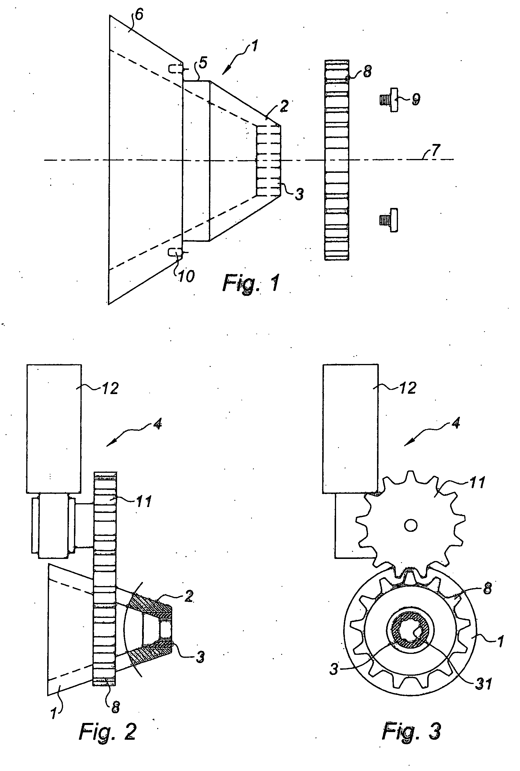
[0029] The equipment for twisting the fibres will now be described with reference to FIGS. 1-5. As illustrated in FIG. 1, the equipment comprises a bowl 1, which drives the fibres in rotation, and which can also be referred to as a funnel, of conical shape, made of plastic or of metal, having a twisting die 3 in its narrowed downstream part 2. The whole arrangement can be referred to as a whistle. The bowl 1 can be driven in rotation by a gear mechanism 4, as shown in FIG. 2.
[0030] An annular shoulder 5 is formed in the wall 6 of the bowl 1, overall in a transverse plane perpendicular to the axis 7 of the bowl 1, in order to receive the driven pinion 8 of the gear mechanism 4. The driven pinion 8 is fixed by screws 9 which are screwed into orifices 10 in the wall 6 of the bowl 1. The driven pinion 8 meshes with a driving pinion 11, itself driven by a motor 12, so as to form a wheel gear 8, 11.
[0031] In some embodiments, in place of the wheel gear 8, 11, a drive belt is mounted around a driving pulley, integral with the shaft of the motor 12. Further, in some embodiments, a driven pulley is mounted on the bowl 1 in place of the pinion 8.
[0032] The die 3 is a cylindrical die with grooves 31, as shown in FIG. 3. Alternatively have an entirely different design making it possible to secure the fibres and to drive them in a twisting movement, or, to comb them at the periphery to improve the appearance of the final dressing ribbon. It could also be frustoconical. The die is made of stainless steel, for example.
[0033] As shown in FIG. 4, the equipment further comprises a downstream calender 13 and an upstream calender 16. The downstream calender 13 comprises two motorized press rollers 14, 15 for pressing the ribbon emerging from the die 3 and for fixing the shape of the fibres. The downstream roller 13 is used alone when a web 19 emerging from the card is driven in rotation, as illustrated in FIG. 5. When a ribbon of fibres 20 is driven in rotation, the upstream calender 16 thus formed by two motorized press rollers 17, 18 is also used. As such, by passing the ribbon through the two calenders 13, 16 arranged on either side of the bowl 1 and by blocking the ribbon of fibres there, it is possible to limit the zone of twisting.
[0034] Note that the rollers 14, 15, 17, 18 also serve to pull the fibres. With regard to the pressing and fixing in shape of the ribbon emerging from the die, and to provide precise figures, the pressure can vary from 0.5 to 4 bar for densities ranging from 4 to 9 grams per metre and for ribbon diameters ranging from 0.5 to 2 centimetres.
[0035] In the case where the dressing product is obtained directly from a web of fibres 19 emerging from the card, the equipment comprises members for guiding the web. These members include a conveyor belt 21 and nozzles, indicated by arrows 22 in FIG. 6, emitting jets of air at the borders 23, 24 of the web 19, in the direction of its centre. The width of the web influences the appearance of the dressing ribbon; the greater the width, the greater the twisting and the greater the strength of the ribbon.
[0036] Preferably, the die 3 has a diameter slightly smaller than that of the dressing ribbon which one wishes to produce. For example, a dressing ribbon measuring 1 cm in diameter can be obtained using a die whose cross section of passage has a diameter of 0.5 to 1.5 cm. A cross section of 0.6 to 0.8 cm is preferable.
[0037] To obtain the dressing ribbon, downstream of a card from which a web emerges, the fibres, i.e., directly those of the web 19 or those of a ribbon 20 which has been formed beforehand after folding of the web (see, FIG. 4), are introduced into and driven in rotation in the bowl 1. The fibres then pass through the die 3 where they are twisted to form a twisted fibrous ribbon 25, are pressed, and their shape is fixed in the calender 13.
[0038] By virtue of the twisting and peripheral combing, the dressing ribbon will retain better cohesion, particularly in the direction of width, thus avoiding sliding in the lengthwise direction, this making it easier to remove it from the wound completely and without causing pain. The ribbon 25 advantageously comprises a traceable filament 26 placed at the centre and entirely surrounded by fibres, hence invisible from the outside. Although traceable, escape is impossible.
[0039] In each case of producing the dressing ribbon 25, either from the web 19 or ribbon 20, the material moves at constant speed through the equipment and must not experience acceleration, so as not to cause stretching, or even tearing.
[0040] The speed of rotation of the assembly made up of the bowl and the die must be sufficiently fast. Depending on the speed of advance of the material, it is between 50 and 700 revolutions per minute. For example, a speed of the order of 300 revolutions per minute is suitable for an advance of 12 to 36 metres per minute, and preferably of 30 metres per minute.
[0041] The humidity of the material during its shaping also plays an important role in the appearance of the final product. It must be between 28 and 40%, preferably between 30 and 35%. Below these values, the fibres are too dry and do not allow the desired shape to be maintained and, above these values, the fibres are too heavy and too sticky, the ribbon losing its cylindrical shape and remaining flat.
[0042] Tables 1 and 2 below, which summarize the results of tests of tensile strength in the direction of width, reveal the increase in the mechanical strength of the dressing product due to the inventive shaping procedure which has just been described.
[0043] These tests were conducted using a card web with a width of 1 metre, a density of 20 g per m3 and a humidity of 30%. As regards the card web treated according to the invention, the speed of advance was 24 metres per minute, the inlet diameter of the bowl was 11 centimetres, its length 5 centimetres, its outlet diameter (die diameter) 0.7 centimetre. The speed of rotation of the assembly was 300 revolutions per minute and the pressure between the rollers was 1 bar.
[0044] In both cases, i.e. the conventional ribbon and the ribbon of the prior art, a ribbon was formed which was cut into eight sections of 4 cm in length and whose tensile strength was measured, in the direction of width of the ribbon, between the two jaws of a dynamometer. TABLE 1 Conventional Ribbon Tensile strength in width direction in m · kg · s−2 (Newton) Section 1 0.44 Section 2 0.56 Section 3 0.52 Section 4 0.38 Section 5 0.39 Section 6 0.49 Section 7 0.31 Section 8 0.48 Average 0.45
[0045] TABLE 2 Twisted Ribbon Tensile strength in width direction in m · kg · s−2 (Newton) Section 1 0.61 Section 2 0.74 Section 3 0.89 Section 4 0.58 Section 5 0.70 Section 6 1.12 Section 7 0.92 Section 8 0.96 Average 0.82
[0046] On average, the tensile strength of the dressing product according to the invention is almost twice stronger than that of the conventional ribbon.
[0047] Although the present invention and its advantages have been described in detail, it should be understood that the present invention is not limited to or defined by what is shown or described herein. As one of ordinary skill in the art will appreciate, various changes, substitutions, and alterations could be made or otherwise implemented without departing from the principles of the present invention. Accordingly, the scope of the present invention should be determined by the following claims and their legal equivalents.