Tool changer of machine tool

Inactive Publication Date: 2005-06-30
DMG MORI SEIKI CO LTD
View PDF19 Cites 35 Cited by
  • Summary
  • Abstract
  • Description
  • Claims
  • Application Information

AI Technical Summary

Benefits of technology

[0018] In the above-described embodiment, the tool is held to be directed in the direction crossin

Problems solved by technology

Both of the above-described conventional tool changers, however, require a specialized actuator for moving the support table and the tool holder, and further require sep

Method used


Image

  • Tool changer of machine tool
  • Tool changer of machine tool
  • Tool changer of machine tool

Examples


Embodiment Construction

[0030] Hereinafter, an embodiment of the present invention will be described based on the attached drawings.

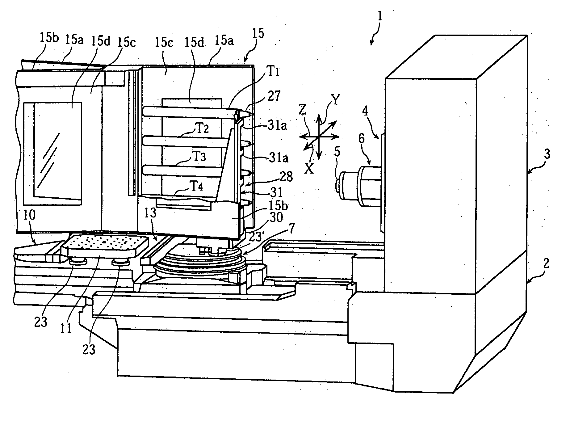
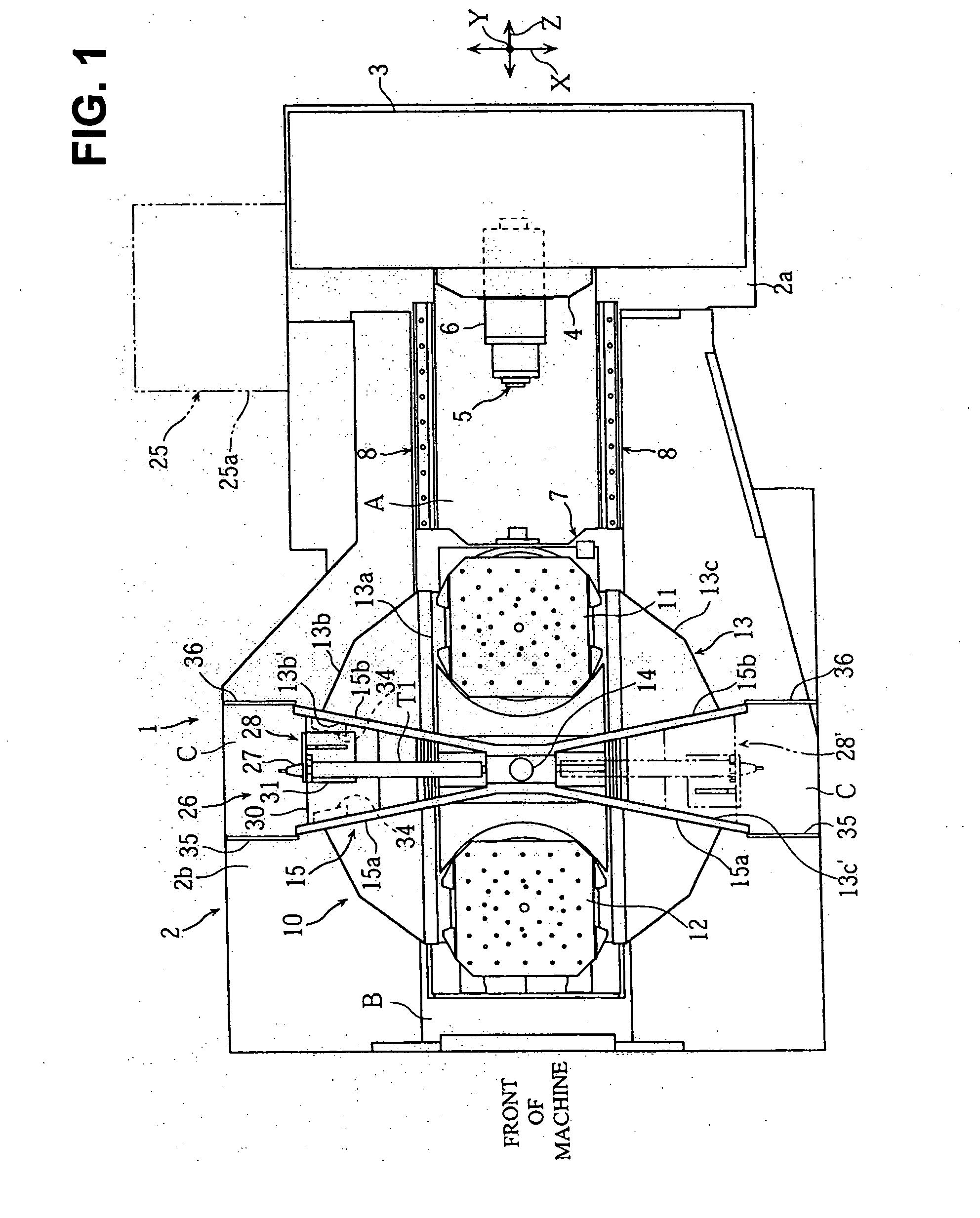
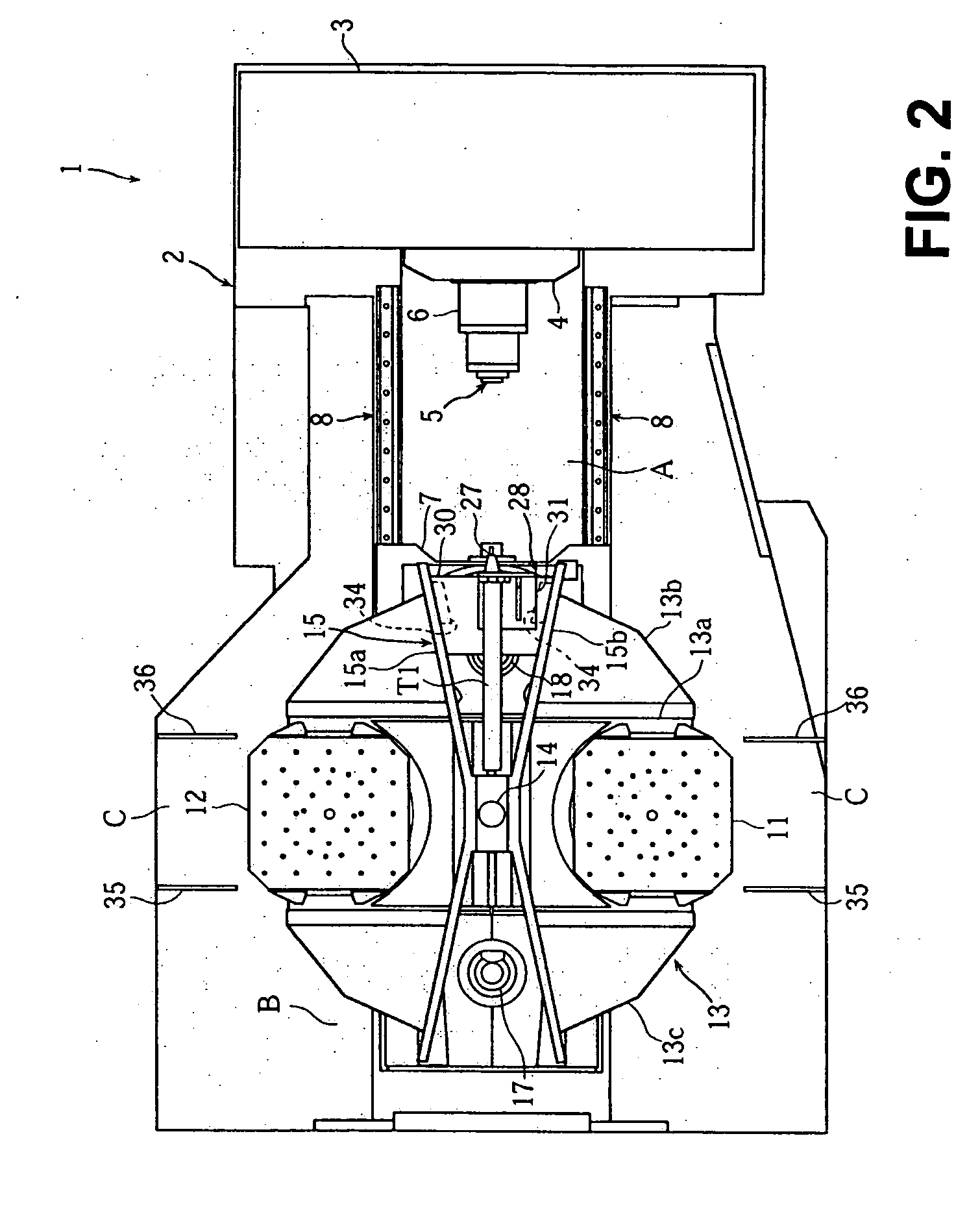
[0031]FIG. 1 to FIG. 11 are views to explain a tool changer of a horizontal machining center (machine tool) according to an embodiment of the present invention. FIG. 1 is a plan view of the horizontal machining center, FIG. 2 to FIG. 6 are plan views showing tool changing operations of the tool changer, FIG. 7 and FIG. 8 are a side view and a perspective view of the horizontal machining center, FIG. 9(a) and FIG. 9(b) are perspective views of the tool magazine, FIG. 10 is a perspective view of a tool holding mechanism and a tool holder, and FIG. 11 is a cross-sectional view of a clamp mechanism of a pallet changer.

[0032] In the drawings, 1 denotes the horizontal machining center. The horizontal machining center 1, when seen from a front side of the machine, is structured such that a substantially rectangular parallelepiped column 3 is fixedly disposed on a back end portion 2...


PUM

PropertyMeasurementUnit
Sizeaaaaaaaaaa

Abstract

The present invention provides a tool changer of a machine tool capable of suppressing cost increase and preventing size increase of the machine when a tool magazine is mounted. In a tool changer of a machine tool provided with a pallet change mechanism 10 in which a machining-side pallet 11 disposed on a machining area A side and a standby-side pallet 12 disposed on a standby area B side are turned around a turn shaft 14 by a turning member 13 to be automatically changed, a tool magazine 28 holding a plurality of tools T1 to T4 is disposed between the machining-side pallet 11 and the standby-side pallet 12 in the turning member 13 and the tool magazine 28 is turned by the turning member 13 so that the tools T1 to T4 face a spindle 5 disposed on the machining area A side.

Description

BACKGROUND OF THE INVENTION [0001] 1. Field of the Invention [0002] The present invention relates to a tool changer of a machine tool provided with a pallet change mechanism in which a machining-side pallet and a standby-side pallet are turned by a turning member around a turn shaft to be automatically changed. [0003] 2. Description of the Related Art [0004] For example, a horizontal machining center sometimes uses, for machining a workpiece, a long tool that is longer than a standard size tool. As an example of a tool changer capable of automatically changing such long tools, there is a tool changer structured such that a support table on which a plurality of long tools are arranged is moved by an actuator between a standby position and a tool change position on a bed, thereby allowing a spindle to grip a required tool (for example, Japanese Utility Model Registration No. 2532663). As another example, there is a tool changer structured such that a gate-shaped frame is installed on ...

Claims


Application Information

Patent Timeline
IPC IPC(8): B23Q1/66B23Q3/155B23Q3/157B23Q7/00
CPCB23Q1/66B23Q3/15526B23Q3/15706Y10T483/179Y10T409/30392Y10T483/16Y10T483/115Y10T29/5196B23Q3/15536
Inventor NAKAZAWA, SHUNSUKEKANEDA, NOBUHIROYASUMURA, RYOSUKE
Owner DMG MORI SEIKI CO LTD
Why Eureka
Try Eureka