Automatic injection device

a technology of automatic injection and injection device, which is applied in the field of contrast medium injection device, can solve the problems of complex valve switching operation, poor device configuration balance, and sometimes forgotten switching operation

Inactive Publication Date: 2005-06-30
NEMOTO KYORINDO KK
View PDF14 Cites 20 Cited by
  • Summary
  • Abstract
  • Description
  • Claims
  • Application Information

AI Technical Summary

Benefits of technology

[0012] The present invention has been devised in order to solve such a problem and it is an object of the present invention to provide an automatic injection device mountable with a plurality of syringes, in which when at least one head is in a state of injection and at least one head is in a stopped state, the backward-moving of the cylinder piston of the stopped head is prevented so as to prevent liquid from undesirably being mixed and the amount thereof from unreliably being injected.
[0014] According to the present invention, when the syringe piston mounted at the second head is in a stopped state, even if the piston holder is moved forward for the injection of a chemical solution in the syringe at a the first head, the backward-moving of the syringe piston at the second head can be prevented. Therefore the chemical solution in the syringe of the first head does not flow into the syringe of the second head, thereby the mixture of the chemical solution can effectively prevented.

Problems solved by technology

However, when a manually operable valve is used for this purpose, the switching operation of the valves is complicated and the switching is sometimes forgotten.
Although it is possible to perform the switching of the valves automatically and electrically, it is not preferable to provide a drive unit of such a switching in the midway through a substantially soft and light tube because the balance of the device configuration become worse.
On the other hand, if a one-way valve is used, the device can be made simple and compact, but the backward-moving action of the syringe piston cannot be performed.
Although an idea can be also conceived that a pressure in the forward direction is applied to the syringe piston at the head B so as to resist the pressure from the side of the head A when the syringe piston at the head B is in a stopped state, the axis of rotation of the motor continues to be in a stopped state while electricity is being supplied to the motor, and there arises a problem of the seizing of the motor.

Method used


Image

  • Automatic injection device
  • Automatic injection device
  • Automatic injection device

Examples


embodiment 1

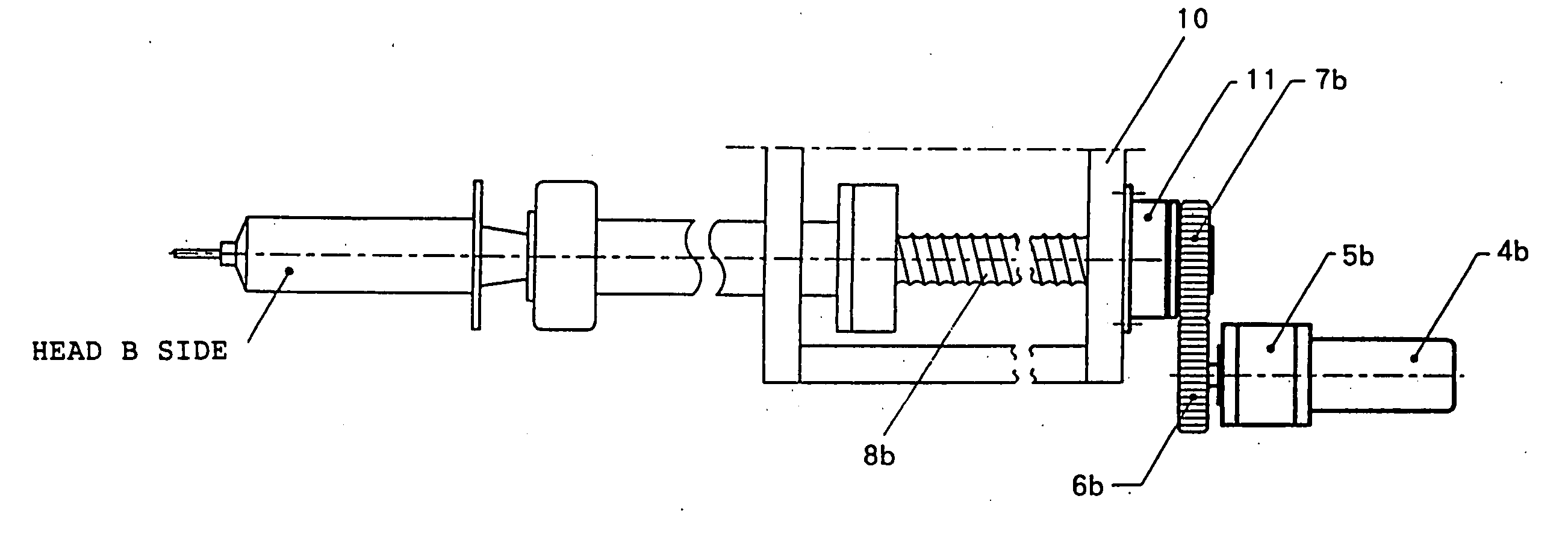
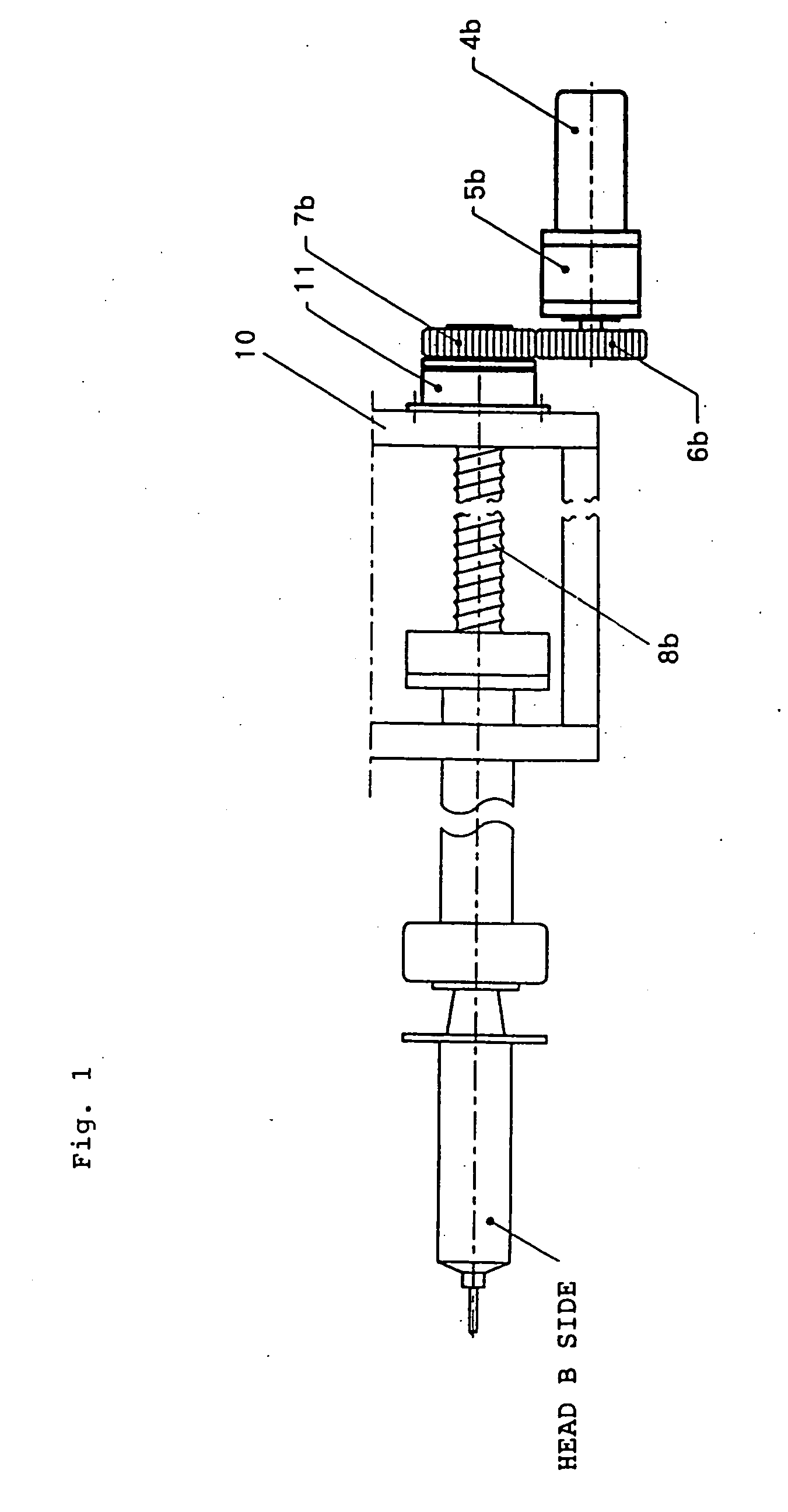
[0054] An example using an electromagnetic brake as backward-moving prohibition mechanism will be described below with reference to FIG. 1.

[0055] In this example, the main body of the electromagnetic brake 11 is fixed to a frame unit 10, while the axis (to which a screw gear 7b is fixed) of a ball screw 8b is fixed to an armature side of the electromagnetic brake. Linking and separation between the main body and the armature is performed by controlling the coil inside the electromagnetic brake.

[0056] When a syringe piston at the side of the head B is moved forward of backward, the main body and the armature are separated each other (i.e. contact is released), thereby the ball screw 8b can rotate freely by receiving the rotation of a motor 4b. When the electromagnetic brake is turned on, the main body and the armature is linked (i.e. contact is attained), thereby the rotation of the axis of the ball screw 8b is fixed. Hence, if the electromagnetic brake is turned on when the syring...

embodiment 2

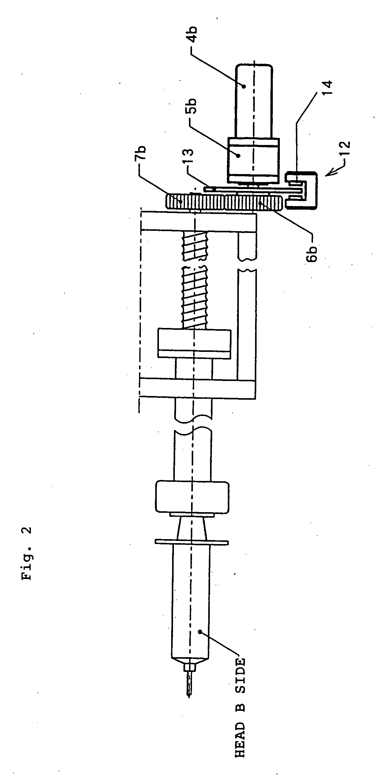
[0057] An example using a disc brake as backward-moving prohibition mechanism will be described below with reference to FIG. 2.

[0058] The disc brake 12 has a disc 13 and pads 14, which stops the rotation of the disc by holding the disc 13 between the pads 14. When the piston syringe at the head B is moved forward and backward, the space between the disc 13 and the pads 14 is left open so that the motor gear 6b can freely rotate. When the backward-moving of the syringe piston at the head B is desired to be prohibited, the disc 13 may be clamped by the pads 14 by electrically controlling the disc brake.

[0059] In this example, though the disc 13 is fixed to the motor gear 6b, it may be fixed to the screw gear 7b or fixed to any place of the axis of rotation.

[0060] In the above-described embodiments 1 and 2, though a method of using the brake was described, other types of brakes other than the electromagnetic brake and the disc brake may be used if the movement in the backward direct...

embodiment 3

[0061] An example using a ratchet mechanism as the backward-moving prohibition mechanism will be described below with reference to FIG. 3.

[0062] As shown in FIG. 3(a), a ratchet 15 is provided on a cylinder portion 19 of a ball nut unit 9b and fitted into a ratchet claw of a ratchet pole 16, making it possible to move forward the syringe piston and prohibit the backward-moving thereof. That is, when at least the motor at the side of the head B is stopped and the ratchet is allowed to engage with the ratchet claw, there is no backward-moving of the syringe piston nor a backward flow. When the syringe piston allows to move backward, a rotary solenoid 17 is electrically controlled so as to rotate the ratchet pole 16, and the engagement of the ratchet and the ratchet claw is released. In FIG. 3(b) (cross-sectional view at line A-A in FIG. 3(a)), a state of the ratchet being engaged with the ratchet claw and a physical relationship of the rotary solenoid 17 are shown.

[0063] The place w...


PUM


Abstract

An automatic injection device has piston holders holding cylinder pistons and plural systems of heads having a drive mechanism for moving the piston holders forward and backward so that the device can hold a plurality of syringes and operates injection or suction in each syringe independently. This device also has a mechanism for prohibiting the backward-moving of the piston holder of a second head when the piston holder of a first head is in a forward-moving state and the piston holder of the second head is in a stopped state. This structure effectively prevents liquid from being undesirably mixed and the injection amount thereof from becoming less accurate.

Description

BACKGROUND OF THE INVENTION [0001] 1. Field of the Invention [0002] The present invention relates to a contrast medium injection device used for X-ray CT image diagnosis, MRI image diagnosis and the like. [0003] 2. Description of the Related Art [0004] A contrast medium is used for the diagnosis of X-ray CT (computed tomography) images, MRI, angio-images (angiographic images) and the like. The contrast medium is a liquid having high viscosity and the injection thereof by means of a manual power takes a lot of time and labor so that in recent years automatic contrast medium injection devices have come to be used. [0005] An automatic injection device 100 of FIG. 8 is an example of such devices, and since it can be mounted with two syringes, it is referred to as a double-head type. FIG. 9 shows a typical mechanism of the automatic injection device. A syringe 1a for the contrast medium is set at the side of a head A, a syringe 1b for a physiological saline solution is set at the side of...

Claims


Application Information

Patent Timeline
Patent Type & Authority Applications(United States)
IPC IPC(8): A61B5/055A61M5/20A61B6/00A61M5/00A61M5/145A61M5/19A61M5/315A61M36/04
CPCA61M5/007A61M5/19A61M5/1456A61M5/2066A61M5/31501A61M5/31511A61M5/31575A61M5/31578A61M5/31596A61M2005/3152A61M2005/1403
Inventor FUKUDA, TAKASHI
Owner NEMOTO KYORINDO KK
Why Eureka
Try Eureka