Lancing device with combination depth and activation control

a technology of activation control and lancing device, which is applied in the field of lancing device, can solve the problems of user's inability single-use lancing device users have little or no ability to adjust the depth and/or size of the wound, and may be forced to suffer the pain of a lancet, so as to reduce the spring load and reduce the vibration of the needle. , the effect of less pain

Inactive Publication Date: 2005-06-30
FACET TECH LLC
View PDF27 Cites 125 Cited by
  • Summary
  • Abstract
  • Description
  • Claims
  • Application Information

AI Technical Summary

Benefits of technology

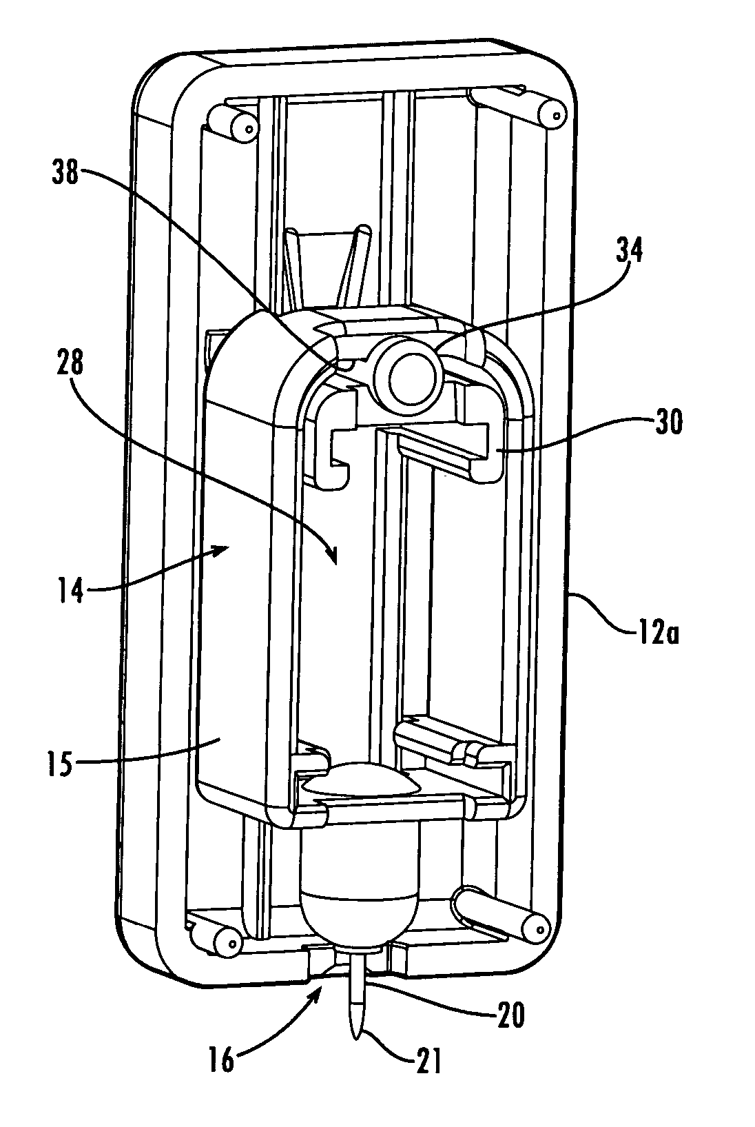
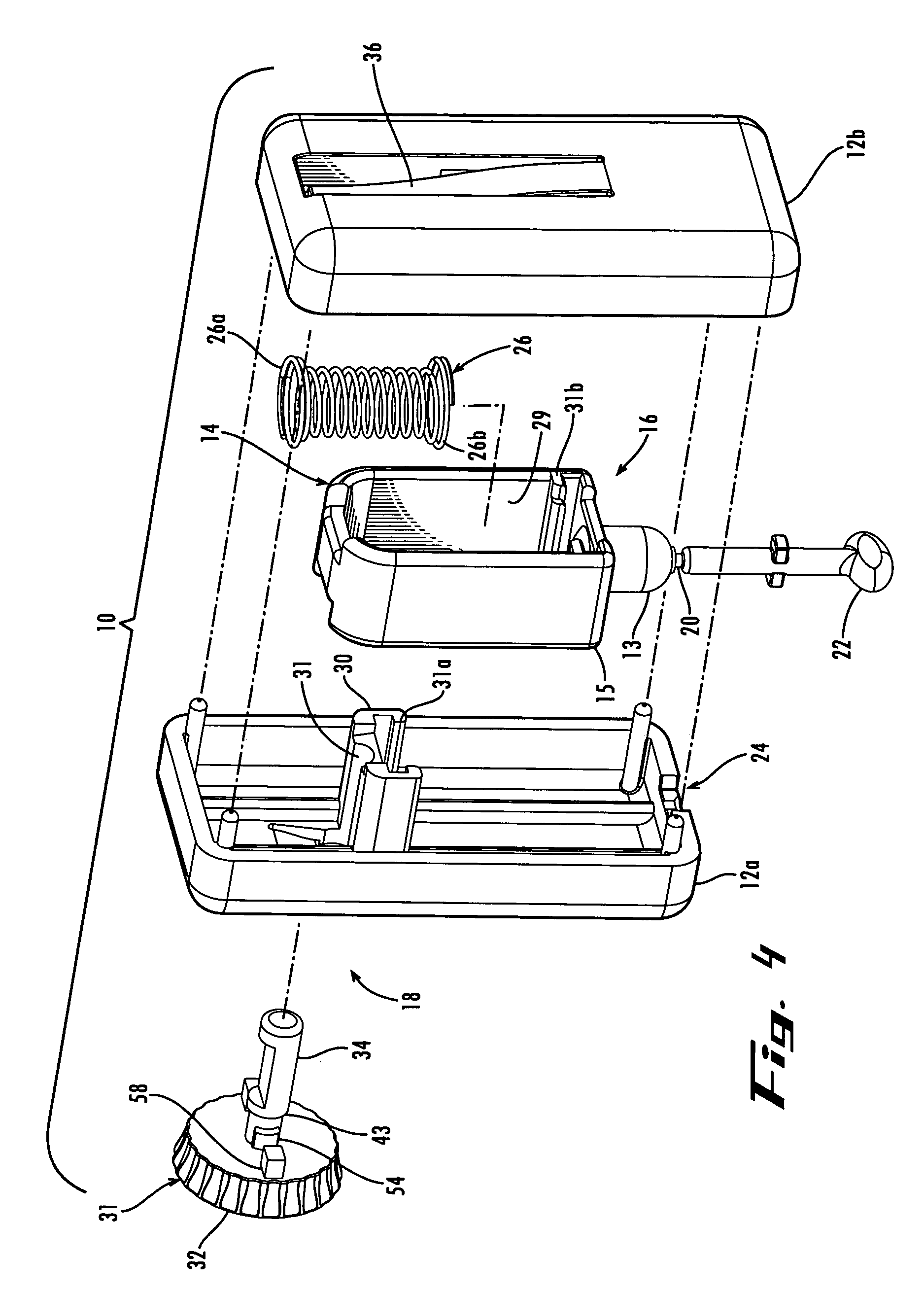
[0011] In another aspect of the invention, the lancet body includes an operating section with an inner wall forming an opening. The spring is positioned within the opening and mounted between the lancet body and the housing. For example, the spring may be mounted to the lancet body inner wall at a forward portion of the lancet body and to the support arm that extends laterally from the housing and into the opening. And the control shaft is supported by the arm so that the stop surfaces are alignable with the engagement surface at a rearward portion of the lancet body. In this way, the travel of the lancet is stopped by the impact of the lancet body engagement surface against one of the stop surfaces, and this impact is rearward and thus remote from the forward portion where the needle is, resulting in a less needle vibration and associated pain.
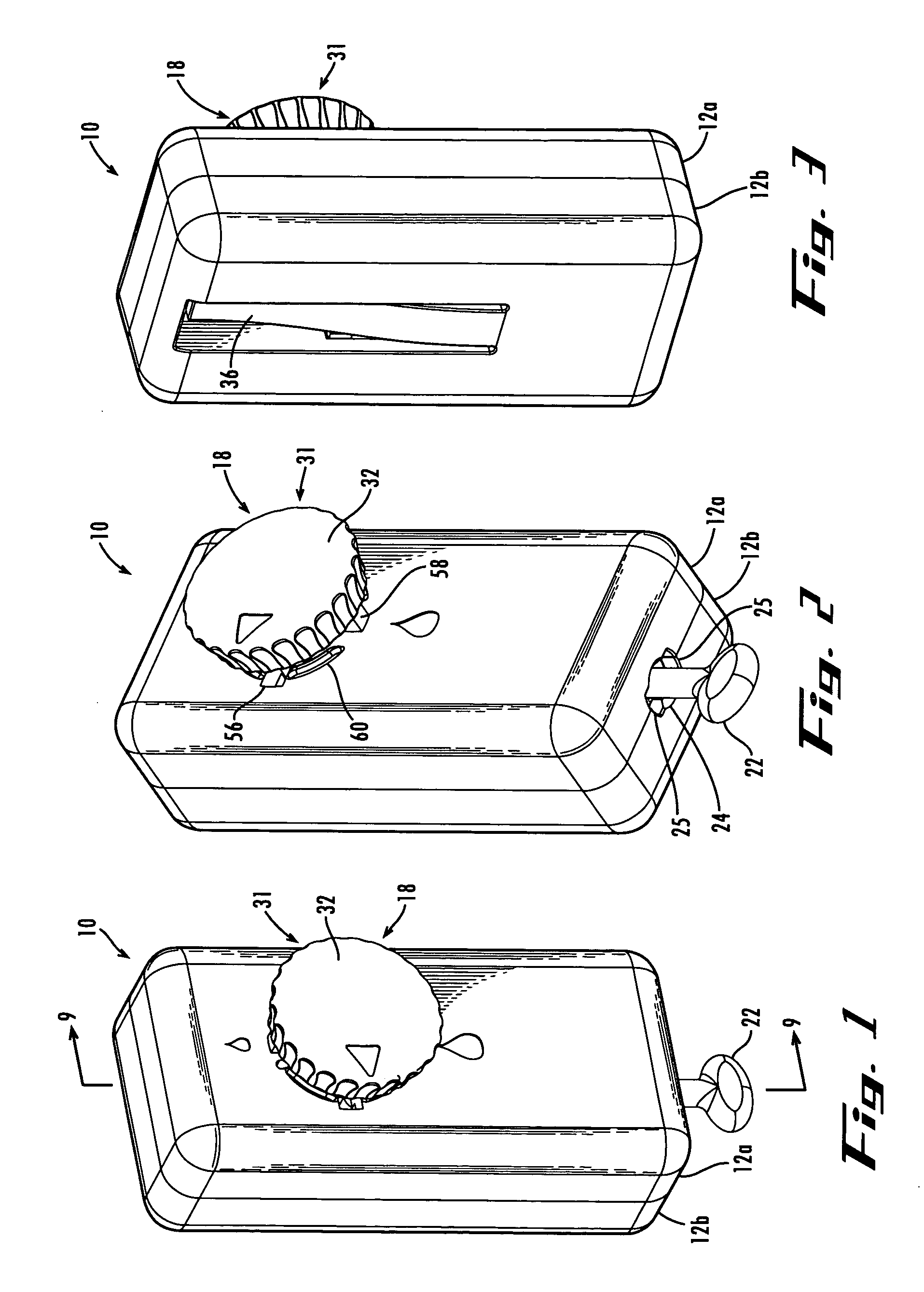
[0012] In yet another aspect of the invention, the lancing device includes a safety interlock feature. The safety interlock includes one or more lock tabs that align with and fit into one or more lock openings when the control knob is in the unlocked depth setting positions. But when the control knob is in the locked position, the lock tabs do not align with and do not fit into the lock openings, so the control knob cannot be depressed. In one example, one lock tab extends radially from the control shaft and the mating lock opening is formed in the housing and in communication with the control opening through which the control shaft extends. And in another example, two lock tabs extend from and are parallel to the control shaft axis, and two mating lock openings are formed in the housing in positions spaced apart from and on opposite sides of the control opening. In this way, the safety interlock prevents the control knob from being depressed when in the locked position, and permits the control knob to be depressed to activate the device when in one of the depth setting positions.
[0013] In still another aspect of the invention, the housing has a plurality of ridges or other protrusions with gaps between them. For example, four ridges may positioned in a generally circular arrangement so that when the control knob is in the locked position or one of the depth setting positions, the lock tabs are positioned in the gaps or the lock openings between the ridges. In addition, the housing may be provided with a deflection member that permits the control member to move laterally slightly out of the housing so it does not bind when engaging the ridges. In this way, the ridges, gaps, and deflection member provide a smoothly operable control member with discrete and readily perceivable depth setting and locked positions.
[0014] And in a further aspect of the invention, the sterility cap is keyed to the housing. For example, the sterility cap may have one or more tabs extending from it, and the housing may have one or more recessed portions that allow the tabs to fit through only when the tabs are aligned with the recessed portions, or vice versa. In this way, the sterility cap can only be removed after it has been manipulated by the user to align the key tabs and recessed portions. And the key tabs help reduce the spring load on the release member, support arm, and lancet body when the device is in the charged position during shipping and storage.

Problems solved by technology

Accordingly, single-use lancing devices oftentimes include a disabling mechanism to prevent accidental or intentional re-use of the device.
For example, known single-use lancing devices typically do not provide for adjustment of the depth of penetration of the lancet needle beneath the surface of the subject's skin.
Accordingly, users of single-use lancing devices have little or no ability to adjust the depth and / or size of the wound in order to control the fluid sample size.
As a result, a user may be forced to suffer the pain of a lancet stick that is deeper than necessary to collect a sample of adequate size, or may need more than one lancet stick to generate a sufficient sample size.
The lack of depth adjustment also renders previously known single-use lancing devices generally unsuitable for use in sampling from different body sites.
Thus, previously known single-use sampling devices render it difficult or impossible for a user to obtain just the proper sample size from a single lancet stick, or to sample from different sites on the body.

Method used


Image

  • Lancing device with combination depth and activation control
  • Lancing device with combination depth and activation control
  • Lancing device with combination depth and activation control

Examples


Embodiment Construction

[0034] The present invention may be understood more readily by reference to the following detailed description of the invention taken in connection with the accompanying drawing figures, which form a part of this disclosure. It is to be understood that this invention is not limited to the specific devices, methods, conditions or parameters described and / or shown herein, and that the terminology used herein is for the purpose of describing particular embodiments by way of example only and is not intended to be limiting of the claimed invention. Also, as used in the specification including the appended claims, the singular forms “a,”“an,” and “the” include the plural, the term “or” means “and / or,” and reference to a particular numerical value includes at least that particular value, unless the context clearly dictates otherwise. Ranges may be expressed herein as from “about” or “approximately” one particular value and / or to “about” or “approximately” another particular value. When suc...


PUM


Abstract

A lancet, a housing for the lancent, and a combination depth and activation control assembly. The lancet includes a needle, a needle-holding section, and an operating section with an opening. A drive spring is mounted within the opening and between the lancet body and the housing. The control assembly includes a control member with a control interface knob and a control shaft. The control shaft has multiple stop surfaces that are alignable with an engagement surface on the lancet body to control the lancing depth. And the control shaft has a release surface that engages the release member to disengage the engagement member to activate the lancing stroke. Additional features includes a safety interlock for preventing accidental activiation of the lancing device, ridges on the housing for providing discrete locked and depth setting positions, and a keyed sterility cap for preventing accidental removal of the cap.

Description

CROSS-REFERENCE TO RELATED APPLICATION [0001] This application claims the priority benefit of U.S. Provisional Patent Application Ser. No. 60 / 526,213, filed Dec. 2, 2003, the entirety of which is hereby incorporated herein by reference for all purposes.TECHNICAL FIELD [0002] The present invention relates generally to medical devices and, more particularly, to a lancing device for penetrating the skin of a human or animal subject for sampling of blood and / or other body fluids. BACKGROUND OF THE INVENTION [0003] Lancing devices are used to penetrate the skin of a subject and obtain a sample of blood or other body fluid, as in the testing of blood sugar levels by diabetics. Typically, a lancet having a sharp point is translationally mounted within a housing portion of a lancing device. The lancet is driven by a spring or other biasing means to cause the sharp point to extend a small distance through an opening in the housing and into the subject's skin, creating a wound from which the ...

Claims


Application Information

Patent Timeline
Patent Type & Authority Applications(United States)
IPC IPC(8): A61B5/15A61B17/14A61B17/32
CPCA61B5/15142A61B5/1411A61B5/150022A61B5/15019A61B5/150259A61B5/150435A61B5/150549A61B5/150564A61B5/150717A61B5/150809A61B5/150816A61B5/150824A61B5/150885A61B5/15113A61B5/15117A61B5/1513A61B5/15144
Inventor STOUT, JEFFREY T.LATHROP, RAY ADAMSLEVAUGHN, RICHARD W.
Owner FACET TECH LLC
Why Eureka
Try Eureka