Dynamic spinal stabilization system

a spinal stabilization and dynamic technology, applied in the field of spinal implant systems, can solve the problems of inability to alter system is susceptible to overloading the disc annulus, and prior systems are not capable of reducing the stiffness of a segment in various loading modes, so as to prevent bone overgrowth and reduce the cross section

Inactive Publication Date: 2005-06-30
SPINEWAVE
View PDF76 Cites 341 Cited by
  • Summary
  • Abstract
  • Description
  • Claims
  • Application Information

AI Technical Summary

Benefits of technology

[0019] In yet another embodiment of the invention, the bone anchor includes an engagement portion having an elongated shank, in which at least the shank and the flexible portion are integral. The flexible portion defines a cross-sectional area along the longitudinal axis of the shank that is substant...

Problems solved by technology

However, spinal fusion has been recognized to have limitations in the treatment of disc degeneration, especially in the earlier stages of the degeneration where it may be unnecessary to eliminate motion of the spinal motion segments.
Consequently, many of these systems are susceptible to over-loading the disc annulus or are, by necessity, unduly restrictive with respect to motion of the spinal segment.
Moreover, these prior ...

Method used


Image

  • Dynamic spinal stabilization system
  • Dynamic spinal stabilization system
  • Dynamic spinal stabilization system

Examples


Embodiment Construction

[0053] While the invention has been illustrated and described in detail in the drawings and foregoing description, the same should be considered as illustrative and not restrictive in character. It is understood that only the preferred embodiments have been presented and that all changes, modifications and further applications that come within the spirit of the invention are desired to be protected.

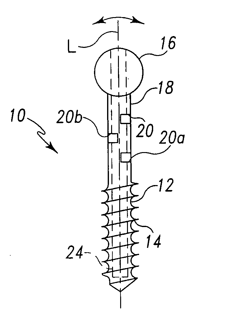
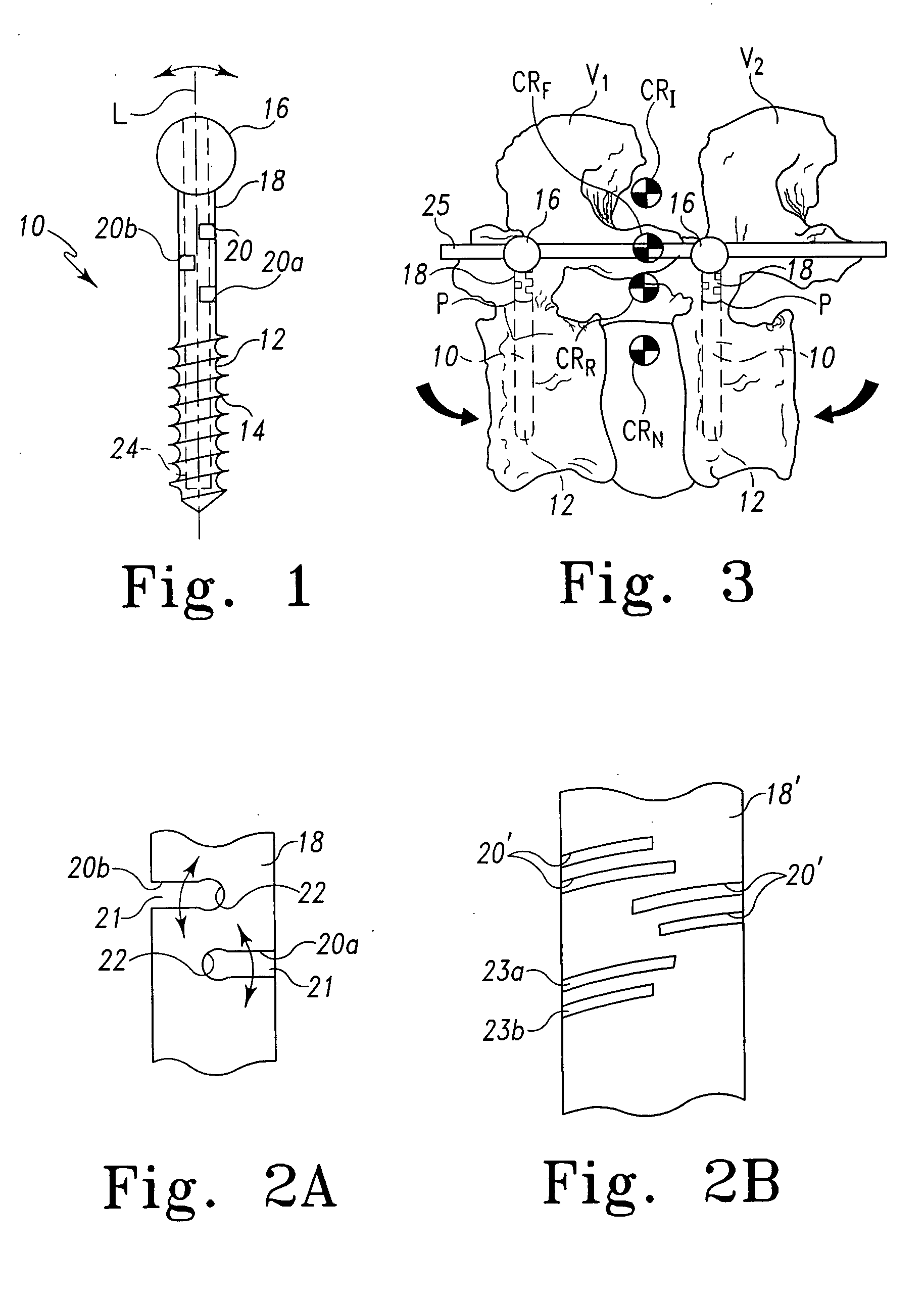
[0054] The present invention contemplates a bone fastener or anchor that is configured to engage a portion of a vertebra and to connect to a stabilization element adapted to span across a spinal motion segment. The bone anchor includes a flexible portion between the vertebra and the stabilization element that permits limited movement of the instrumented vertebrae without commensurate movement of the stabilization element.

[0055] In accordance with one embodiment of the invention shown in FIG. 1, a bone anchor 10 is provided that has an engagement portion 12 which may be an elongated shan...


PUM


Abstract

A dynamic stabilization construct for implantation within the spine comprises bone anchors that include a flexible portion between the bone engaging and head portions of the anchor. The head portion is configured to mate with different types of stabilization elements adapted to span between spinal motion segments. The engagement portion can also be configured for different types of fixation to a motion segment, such as within the pedicle of a vertebra. The flexible portion permits limited bending of the bone anchor beneath the level of the stabilization element. In one embodiment, the flexible portion is integrated into the body of the bone anchor in the form of hinge elements. In another embodiment, a separate flexible element, such as a spacer or spring, is interposed between the head and engagement portions. In a further embodiment, the bone anchor includes a portion having a reduced cross-section. The flexible bone anchors may be used to tailor the dynamic flexibility of spinal stabilization instrumentation at each level of the construct.

Description

[0001] The present invention relates to spinal implant systems, and particularly systems for stabilization of the spine. The invention provides a dynamic stabilization system that permits limited relative movement between the instrumented vertebrae and the stabilization system. [0002] In the past, the principal protocol for the treatment of the spine has been rigid fixation combined with fusion of the affected vertebral body or intervertebral disc. Arthrodesis, as this approach is known, has been achieved with a variety of rigid fixation elements, such as spinal rods or plates that are rigidly fixed to a vertebra using bone screws, bone bolts and spinal hooks. However, spinal fusion has been recognized to have limitations in the treatment of disc degeneration, especially in the earlier stages of the degeneration where it may be unnecessary to eliminate motion of the spinal motion segments. [0003] Clinical studies suggest that cells of the intervertebral disc respond favorably to red...

Claims


Application Information

Patent Timeline
IPC IPC(8): A61B17/70A61B17/86A61B19/00A61F2/44
CPCA61B17/7007A61B17/701A61B17/7032A61B17/7034A61B17/7037A61B17/7053A61F2002/444A61B17/864A61B17/866A61B17/8685A61B17/869A61B2019/301A61F2/442A61B17/8605A61B2090/031
Inventor BOYD, LAWRENCE M.LIPSCHULTZ, TYLER P.LOGUIDICE, MARK D.CARTER, ANDREW
Owner SPINEWAVE
Why Eureka
Try Eureka