
Scheduler, method and program for scheduling, and apparatus for high-level synthesis

a scheduling method and high-level synthesis technology, applied in the direction of program control, cad circuit design, instruments, etc., can solve the problems of insufficient reuse of design and impossible optimal scheduling

Inactive Publication Date: 2005-06-30
KK TOSHIBA
View PDF6 Cites 10 Cited by
  • Summary
  • Abstract
  • Description
  • Claims
  • Application Information

AI Technical Summary

Benefits of technology

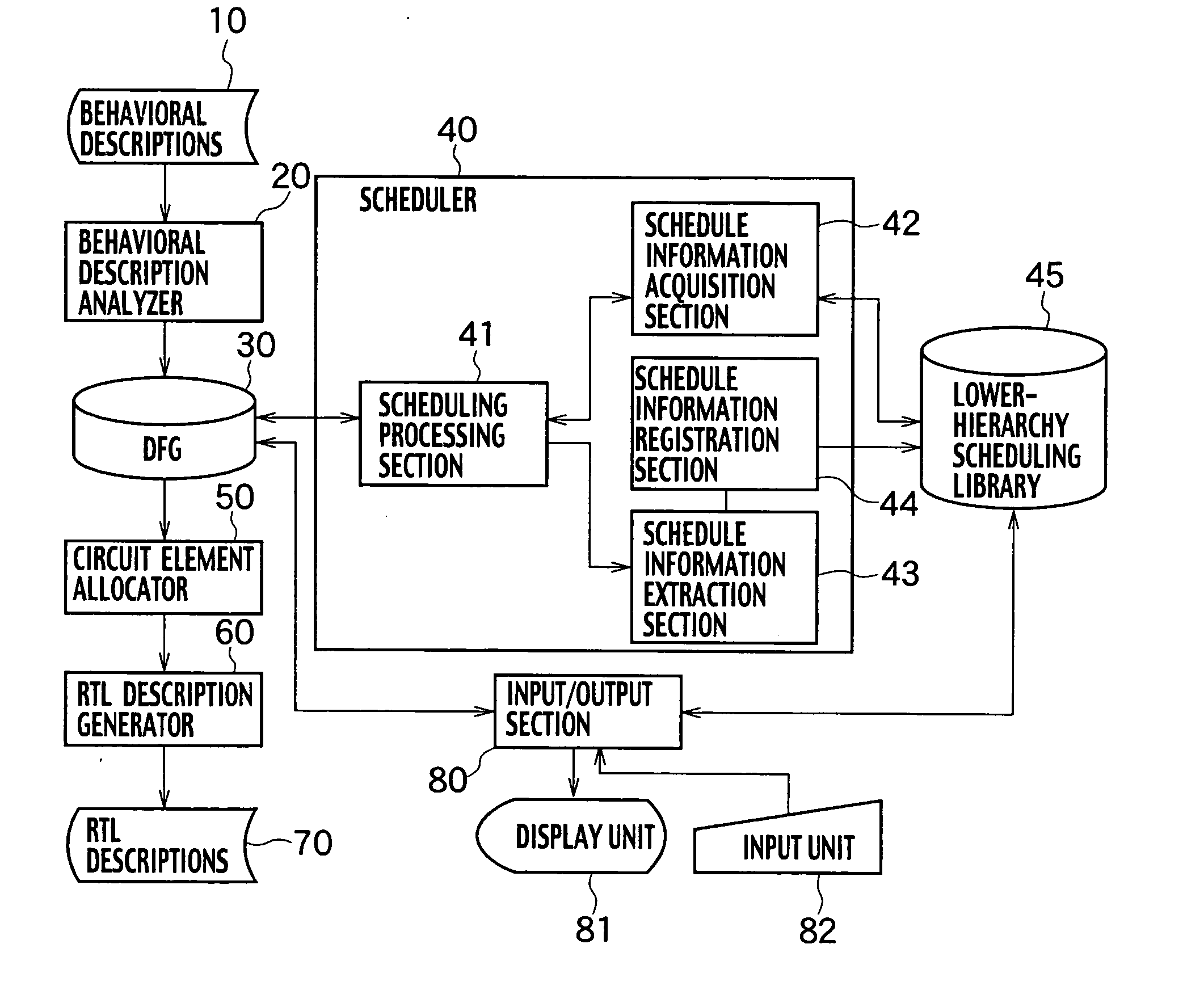
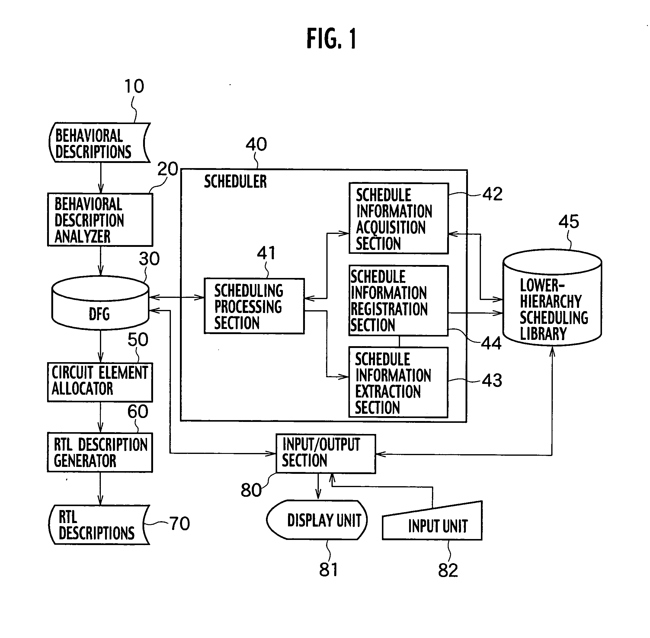
[0015] An apparatus for high-level synthesis according to an embodiment of the present invention includes: a behavioral description analyzer configured to analyze behavioral descriptions describing behavioral operations of a logic circuit under design and to generate a data-flow graph; scheduler configured to partition behavioral operations in the data-flow graph into groups executed in each clock cycle; a circuit element allocator configured to allocate each behavioral operation already scheduled of the data-flow graph to each circuit element of the logic circuit; and an RTL description generator configured to generate register transfer level descriptions based on an allocation results of the circuit elements. The scheduler includes: a schedule information acquisition section configured to acquire the number of first clock cycles and the number of second clock cycles as s

Problems solved by technology

In the above scheduling method, since it was not enough considered that the fact of the matter is that parallel execution is possible between the upper-hierarchy and the lower-hierarchy, there was a problem that the optimum scheduling is impossible.
Therefore, there was also a problem that it is scheduled in series so that execution of the function called second is started after execution of the function called first is completed.
Therefore, there was also a problem that design was not fully reusable.

Method used


Image

  • Scheduler, method and program for scheduling, and apparatus for high-level synthesis
  • Scheduler, method and program for scheduling, and apparatus for high-level synthesis
  • Scheduler, method and program for scheduling, and apparatus for high-level synthesis

Examples


first embodiment

Scheduling Processing in First Embodiment

[0067] Next, the scheduling processing performed by the scheduler 40 will be explained in detail herein below.

[0068]FIG. 3 shows an example of behavioral descriptions to be scheduled expressed graphically by a data flow graph (DFG). In FIG. 3, each of the circular figures expresses an operation; and the operations 201, 202, 203, 205 and 206 express the typical operations, such as an addition or the like. The operation 204 is an operation calling a function “g” belonging to a lower-hierarchy. Each solid line to connect between the circular figures of the operations expresses the data dependency between the operations. For example, the solid line connecting the operation 202 and the operation 203 means that the operation 203 uses an arithmetic result of the operation 202. Therefore, the function “g” belonging to the lower-hierarchy inputs an arithmetic result of the operation 201 and an arithmetic result of the operation 203, and then outputs ...

second embodiment

Scheduling Processing in Second Embodiment

[0094] Next, the scheduling processing performed by the scheduling processing section 41 at the time of scheduling the functions belonging to the lower-hierarchy will be explained in detail herein below. In addition, FIG. 12 shows an example of a scheduling algorithm performed by the scheduling processing section 41 at the time of scheduling the functions belonging to the lower-hierarchy. FIG. 13 shows the scheduling algorithm shown in FIG. 12 described by using the programming language such like C language. Detailed explanation will be described herein below according to an example of behavioral descriptions of function “g” belonging to the lower-layer shown in FIG. 14.

[0095] First, in Step S901, the scheduling processing section 41 stores all operations vi (operations INPUT1, INPUT2, INPUT3, OP1, OP2, OP3, OUTPUT1 and OUTPUT2 shown in FIG. 14) in a Set V.

[0096] Next, in a loop processing [LOOP-1] from Step S902 to Step S909, the scheduli...

third embodiment

Scheduling Processing in Third Embodiment

[0108] Next, the scheduling processing performed by the scheduler 40 in the case where the two or more schedule information of one function belonging to the lower-hierarchy are stored in the lower-hierarchy scheduling library 45 will be explained in detail herein below.

[0109]FIG. 16 shows an example of behavioral descriptions of a function “g” belonging to the lower-hierarchy. It is assumed that operation OP1 and operation OP2 are the operations that can be executed by the same arithmetic circuit. Furthermore, it is assumed that two or more kinds of scheduling results are obtained by scheduling of the behavioral descriptions of the function “g” by the scheduling processing section 41.

[0110]FIG. 17 shows an example of first scheduling results (SCHEDULING 1). In the first scheduling process, the scheduling processing section 41 schedules in order that: all three inputs (INPUT1, INPUT2 and INPUT3) are inputted from the same input pins; operati...


PUM


Abstract

A scheduler includes: a schedule information acquisition section configured to acquire the number of first clock cycles and the number of second clock cycles as schedule information of a function belonging to a lower-hierarchy, the number of the first clock cycles being the number of clock cycles after an execution of the function is started until an input data of the function is used, the number of the second clock cycles being the number of clock cycles after an output data of the function is outputted until the execution of the function is completed; and a scheduling processing section configured to obtain operations executable in the first clock cycles and operations executable in the second clock cycles from among operations belonging to an upper-hierarchy for calling the function, based on the acquired schedule information, and to schedule the upper-hierarchy ensure that the obtained operations execute in parallel with the function.

Description

CROSS REFERENCE TO RELATED APPLICATIONS [0001] This application claims benefit of priority under 35 USC §119 to Japanese Patent Application No. 2003-427452 filed on Dec. 24, 2003, the entire contents of which are incorporated by reference herein. BACKGROUND OF THE INVENTION [0002] 1. Field of the Invention [0003] The present invention pertains to a scheduler, a scheduling method, a scheduling program and a high-level synthesis apparatus for automatically synthesizing a logic circuit from behavioral descriptions. [0004] 2. Description of the Related Art [0005] The scale of a system which can be mounted on one chip has increased as semiconductor technology develops. For this reason, a high-level synthesis methodology as a means for designing a large-scale system in a short period of time is disclosed in “HIGH-LEVEL SYNTHESIS Introduction to Chip and System Design”, Daniel D. Gajski et al., Kluwer Academic Publishers, 1992, and is further disclosed in Japanese patent Laid Open Publicat...

Claims


Application Information

Patent Timeline
IPC IPC(8): G06F17/50
CPCG06F17/5045G06F30/30
Inventor IMAI, HIROSHI
Owner KK TOSHIBA
Learn More