
Structure and method of connecting I-type prestressed concrete beams using steel brackets

a technology of prestressed concrete and steel brackets, which is applied in the direction of bridges, bridge erection/assembly, bridge construction, etc., can solve the problems of imposing excessive construction costs on users, cracks around cold joints, and structural defects, etc., to achieve the effect of higher structural durability

Inactive Publication Date: 2005-07-07
DONGYANG CONSTR
View PDF6 Cites 11 Cited by
  • Summary
  • Abstract
  • Description
  • Claims
  • Application Information

AI Technical Summary

Benefits of technology

[0009] Accordingly, the present invention has been made keeping in mind the above problems occurring in the prior art, and an object of the present invention is to provide a structure and a method of connecting a plurality of PSC-I beams to each other using end plates and steel brackets which have higher structural durability, different from a conventional structure for connecting the plurality of PSC-I beams using only the reinforcing bars and concrete, so that the plurality of PSC-I beams are firmly connected to each other.
[0010] Another object of the present invention is to provide an structure and method of connecting the plurality of PSC-I beams, which has only one support bearing on each of piers to support the PSC-I beams, thus solving the disadvantages caused by using the plurality of support bearings in the prior art.

Problems solved by technology

Thus, the conventional beam connecting structure imposes excessive constructing costs on users.
Therefore, a crack may be generated around the cold joint by the live load.
Thus, structural defect may be caused in the bridge with the conventional beam connecting structure.
However, the conventional beam connecting structure does not have sufficient strength for resistance against the above-mentioned negative moment.

Method used


Image

  • Structure and method of connecting I-type prestressed concrete beams using steel brackets
  • Structure and method of connecting I-type prestressed concrete beams using steel brackets
  • Structure and method of connecting I-type prestressed concrete beams using steel brackets

Examples


Embodiment Construction

[0026] Hereinafter, embodiments of the present invention will be described in detail with reference to the attached drawings.

[0027] Reference now should be made to the drawings, in which the same reference numerals are used throughout the different drawings to designate the same or similar components.

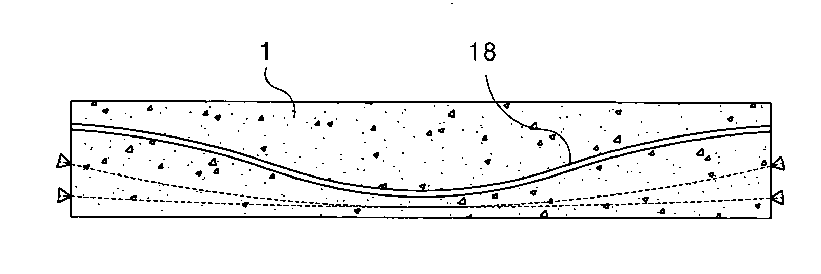
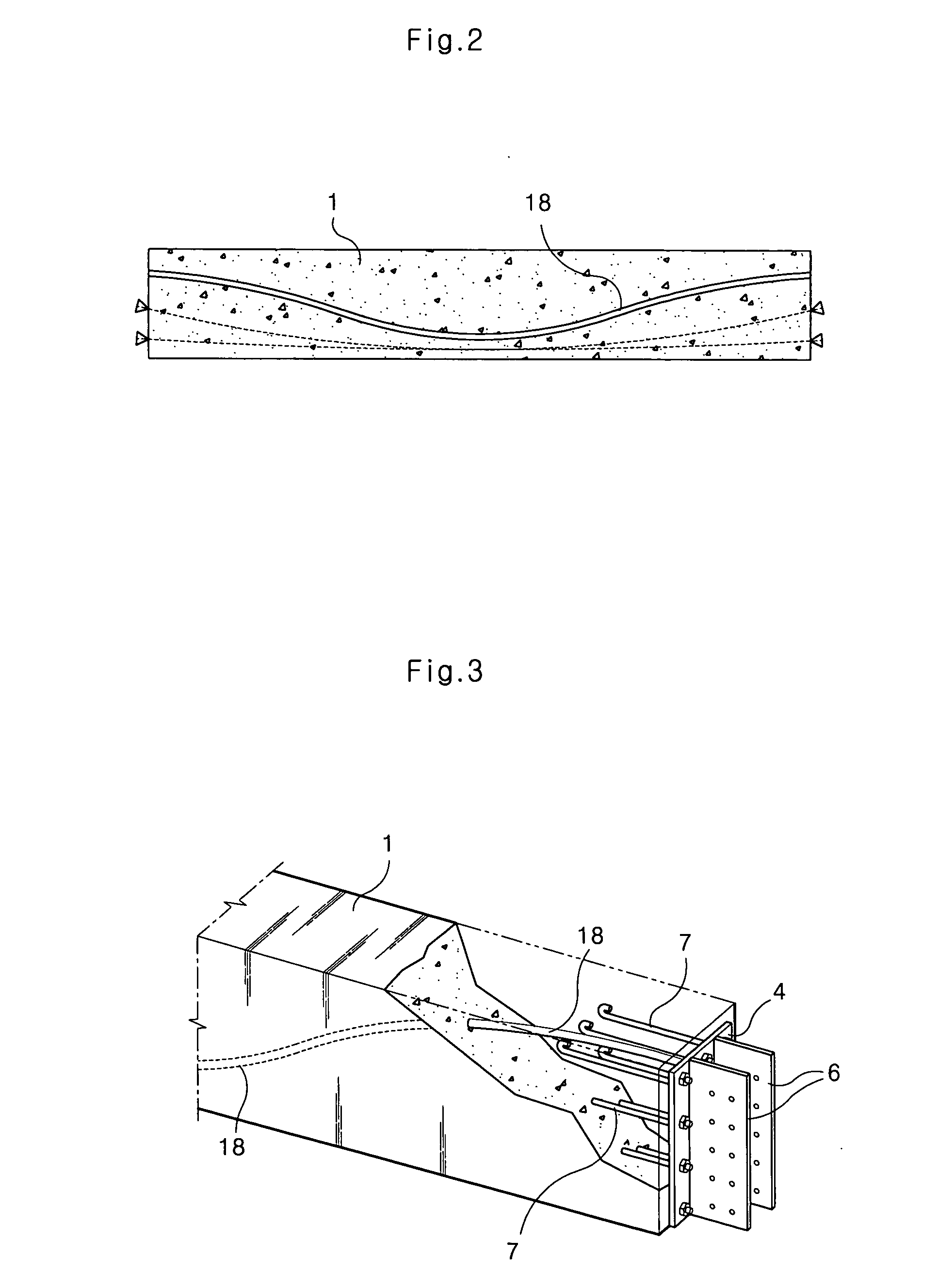
[0028]FIG. 2 is a sectional view of one of a plurality of I-type prestressed concrete beams 1 (PSC-I beams) connected to each other with a structure for connecting the plurality of PSC-I beams, according to an embodiment of the present invention. FIG. 3 is a partially broken perspective view of the PSC-I beam 1 of FIG. 2, in which a part around an end of the PSC-I beam 1 is shown. As shown in FIGS. 2 and 3, in the beam connecting structure according to the present invention, each of the PSC-I beams, made of concrete, has a sheath pipe 18 therein. That is, when the PSC-I beam 1 is produced, the sheath pipe 18 is previously embedded in the concrete. The sheath pipe 18 receives therein a...


PUM


Abstract

A structure and method of connecting a plurality of PSC-I beams (PSC-I beams) to each other using steel brackets. The beam connecting structure, each having a sheath pipe therein, includes an end plate which is mounted on each of both ends of each of the PSC-I beams, with a through hole provided on an upper portion of the end plate to correspond to the sheath pipe embedded in each of the PSC-I beams; a steel bracket integrally which is provided on the end plate to be perpendicular to the end plate; a bracket coupling plate to integrally couple the aligned steel brackets to each other; a bottom connecting plate which is provided on lower ends of the aligned steel brackets to connect the steel brackets to each other; a connecting sheath pipe which is provided between the PSC-I beams so that both ends of the connecting sheath pipe are respectively inserted into the through holes of the neighboring end plates of the PSC-I beams while the PSC-I beams are arranged linearly; a prestress strand which is inserted in the sheath pipes of the PSC-I beams and the connecting sheath pipe; and a concrete part which is filled in a space between the PSC-I beams to embed the aligned steel brackets, the bracket coupling plate and the connecting sheath pipe in the concrete part.

Description

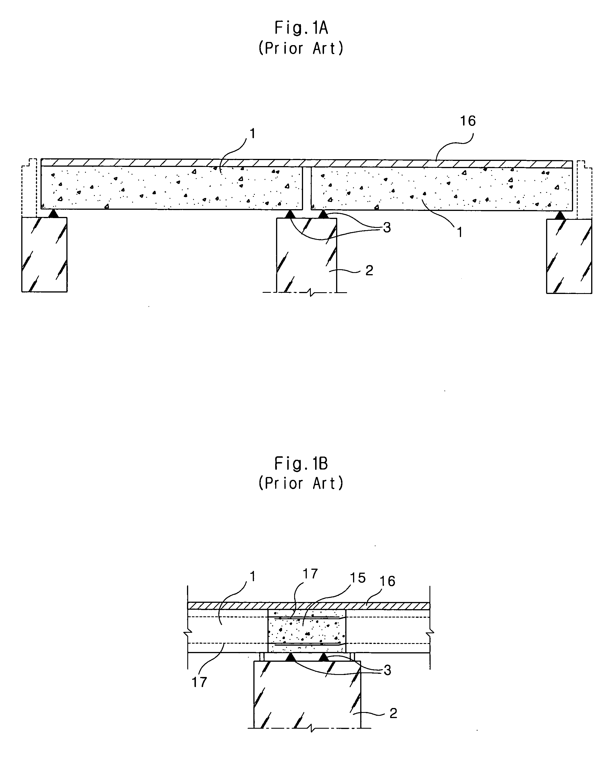
BACKGROUND OF THE INVENTION [0001] 1. Field of the Invention [0002] The present invention relates generally to a structure and a method of connecting I-type prestressed concrete beams (hereinafter referred to simply as PSC-I beams) using steel brackets, and more particularly, to a structure and a method of connecting a plurality of PSC-I beams, separately precasted on the ground, to each other using steel brackets. [0003] 2. Description of the Related Art [0004]FIG. 1A is a side view of a two-span bridge with a conventional structure for connecting two I-type prestressed concrete beams 1 (PSC-I beams) to each other. The two PSC-I beams 1, used in the conventional two-span bridge of FIG. 1A, are separately precasted on the ground. Thereafter, each of the PSC-I beams 1 is independently placed between a pier 2 and a pair of support grounds, which support both ends of the two-span bridge, to form a simple beam system. At this time, the two PSC-I beams 1 are connected to each other by on...

Claims


Application Information

Patent Timeline
IPC IPC(8): E01D2/00E01D2/02E01D1/00E01D21/00E01D101/24E04B1/21E04B1/58
CPCE01D2/00E01D2101/285E01D2/02
Inventor KIM, WON-KEUNKIM, MOON-PALSHIN, HYUN-KEEPARK, SEOUNG-KYOOKIM, TAE-HYOUNGSON, YOUNG-HO
Owner DONGYANG CONSTR
Learn More