Whole-span prefabricated H-steel-concrete composite beam bridge and construction method

A prefabricated installation, H-beam technology, used in the erection/assembly of bridges, bridges, bridge parts, etc., can solve the problems of increasing dead load, difficult quality control, hidden safety hazards, etc., to reduce the processing workload, save materials and Process, the effect of enhancing the durability of the structure

Inactive Publication Date: 2018-07-31
CHONGQING JIAOTONG UNIVERSITY
View PDF4 Cites 8 Cited by
  • Summary
  • Abstract
  • Description
  • Claims
  • Application Information

AI Technical Summary

Problems solved by technology

[0003] The main advantage of the above method is that the transportation and hoisting weight is light, and the hoisting equipment is relatively low, but there are still the following problems: on the one hand, the traditional I-shaped steel plate girder has a large welding workload, high precision requirements, difficult quality control, and processing costs. high, and it is difficult to avoid the fatigue problem of on-site welding or bolting transverse joints, and there are potential safety hazards in the later stage; on the other hand, the problem is that the on-site workload is large, the construction period is long, and the production cost is high; the transverse connection between beams is implemented on the pier It is difficult to guarantee the quality of concrete for pouring and pouring bridge slabs (joints); installing steel girders first, and then installing joint concrete bridge slabs still has the unfavorable working condition that the self-weight of the beam body is only borne by the I-shaped steel beams, and the steel consumption is large; the existing The construction method of the composite girder bridge must also add a concrete bridge deck pavement layer to ensure that the bridge deck reaches the required flatness, which increases the dead load and a construction process

Method used


Image

  • Whole-span prefabricated H-steel-concrete composite beam bridge and construction method
  • Whole-span prefabricated H-steel-concrete composite beam bridge and construction method
  • Whole-span prefabricated H-steel-concrete composite beam bridge and construction method

Examples


Embodiment Construction

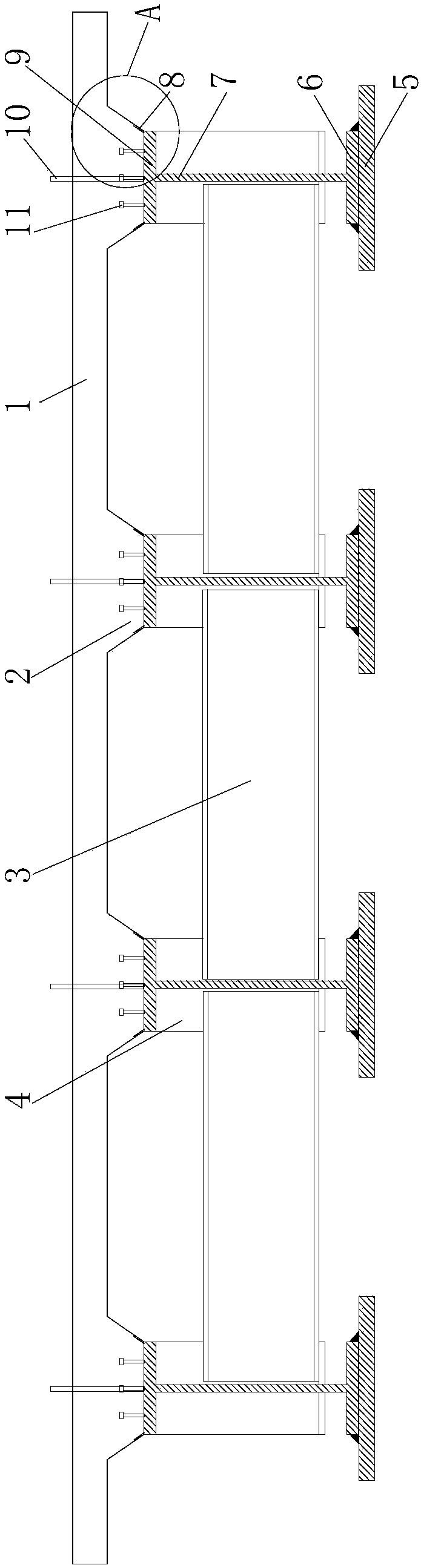
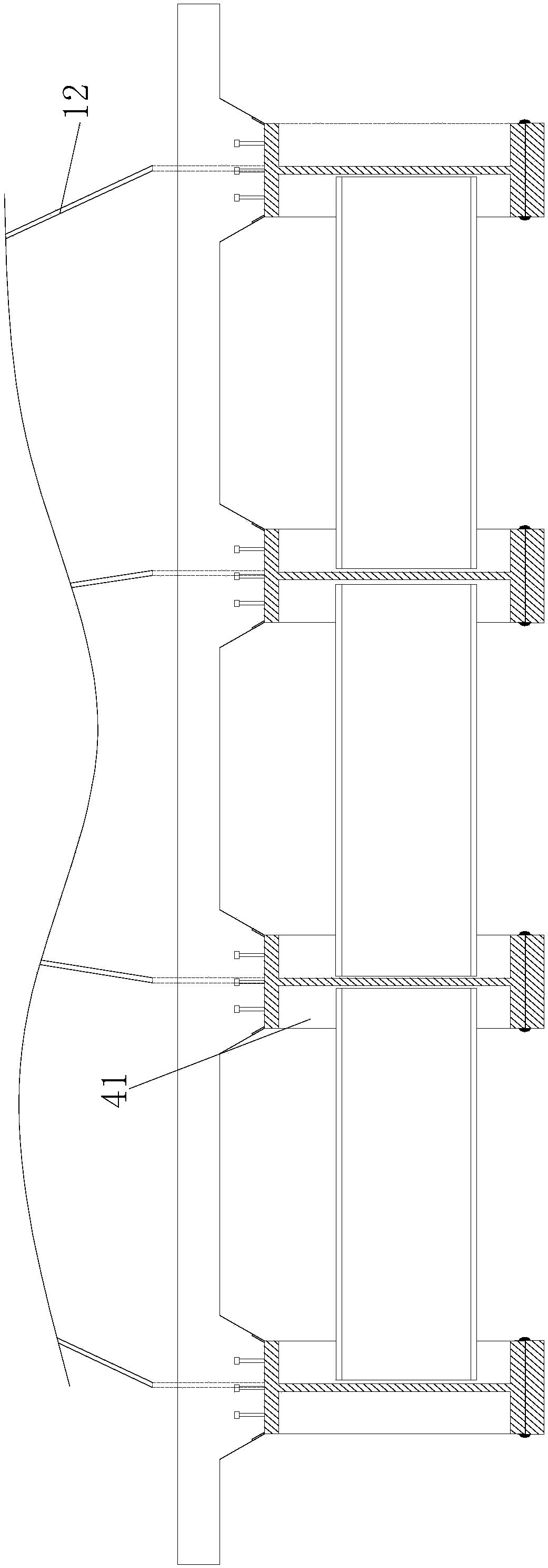
[0027] figure 1 It is a schematic diagram of the cross-sectional structure of the mid-span section of the present invention, figure 2 for figure 1 Enlarged view at A, image 3 It is a schematic diagram of the cross-sectional structure of the pier top support section of the present invention, Figure 4 for figure 1 The schematic diagram of the longitudinal structure, as shown in the figure: the whole-span prefabricated H-shaped steel-concrete composite girder bridge of the present embodiment includes an H-shaped steel combination and a concrete bridge slab 1 poured on the H-shaped steel combination, and the H-shaped steel combination It includes H-shaped steels arranged side by side along the bridge width direction, and the H-shaped steels are the entire span length along the length direction. The steel girder adopts H-shaped steel, which is the whole length of the H-shaped steel beam when it leaves the factory, without welding, which can significantly reduce the cost of t...


PUM


Abstract

The invention discloses a whole-span prefabricated H-steel-concrete composite beam bridge and a construction method. The whole-span prefabricated H-steel-concrete composite beam bridge comprises an H-steel combination and a concrete bridge plate which is poured on the H-steel combination; the H-steel combination comprises H-steels placed in parallel in the bridge width direction; and the whole-span length is the length direction of the H-steels. The whole-span prefabricated H-steel-concrete composite beam bridge has the advantages that the construction of a bridge deck slab is simple and the hoisting weight of the bridge deck slab is light; during making, factory machining and manufacturing procedure does not exist and the later mounting and erecting difficulty is reduced; and meanwhile, as the H-steels can avoid adverse effects such as welding residual stress, more stable mechanical property, better bearing capacity and better durability are obtained; and the making cost can be greatly reduced. Compared with the steel plate girder in the prior art, the whole-span prefabricated H-steel-concrete composite beam bridge has the advantages that the welding or bolting process can be eliminated; construction processes uneasy to control, such as prestressed structure steel strand tensioning and grouting, hollow slab girder hinge joint connection and so on do not exist; the quality of aprofiled-steel composite beam can be effectively guaranteed; and requirements on equipment and technical skills of workers can be reduced.

Description

technical field [0001] The invention belongs to the field of bridge engineering, in particular to a whole-span prefabricated H-shaped steel-concrete composite beam bridge and a construction method. Background technique [0002] The I-beams used in existing composite girder bridges are generally factory-made and welded to form I-steel girders. After transporting to the site, each I-steel girder is installed sequentially on the pier and abutment. Component connection, re-casting the concrete bridge slab or installing the block prefabricated bridge slab and then casting the vertical and horizontal wet joints to form a steel-concrete composite beam bridge; or first pouring the concrete upper wing on the I-beam to form a single For I-beam-concrete composite beams, the composite beams are installed in sequence on the pier, and the horizontal connection between the composite beams is implemented on site, and the longitudinal wet joints of the composite beam bridge slabs are reprodu...

Claims


Application Information

Patent Timeline
Patent Type & Authority Applications(China)
IPC IPC(8): E01D2/02E01D19/12E01D21/00
CPCE01D2/02E01D19/125E01D21/00
Inventor 周劲宇蒋俊彦周志祥
Owner CHONGQING JIAOTONG UNIVERSITY
Why Eureka
Try Eureka