Apparatus for measuring green-speed

a technology of green-speed measurement and equipment, applied in the field of equipment for measuring green-speed, can solve the problems of direct errors in green-speed measurement, large variation in roll distance, and inaccuracy in green-speed measurement, and achieve the effect of less errors and more accurate and consistent readings

Inactive Publication Date: 2005-07-07
PELZ DAVID T
View PDF5 Cites 10 Cited by
  • Summary
  • Abstract
  • Description
  • Claims
  • Application Information

AI Technical Summary

Benefits of technology

[0015] The green-speed measuring apparatus of the present invention represents an improvement over the conventional Stimpmeter, green-speed measuring device. The present invention provides a green-speed reading apparatus that provides more accurate and consistent readings with less errors.
[0016] The green-speed measuring apparatus includes a three track ramp for rolling three golf balls along parallel, but distinct tracks over the surface of a green being tested. The ramp is raised above the putting surface to a precise 20.2 degree angle relative to the local horizontal using a preconfigured angled level-vial and an adjustable-length leg structure, which mechanically supports the upper start end of the ramp at a fixed position. The local horizontal is defined as a plane perpendicular to the local gravitational vertical vector. Each golf ball sits in a radiused rolling groove against a radiused ball stop and is held in a pre-release starting position by a release trigger holding plate, which is also radiused to hold golf balls in a repeatable position, regardless of ball surface dimple location or size. The ramp has three ball-radiused rolling grooves, which reduce golf ball chatter when a dimpled surface ball tolls down the grooves. The end of the ramp is curved in order to release golf balls horizontally so as to be essentially parallel to the putting green surface thereby minimizing or totally eliminating ball bounce as the ball impacts the surface of the green.
[0017] Other features of the apparatus include a level-vial to accurately determine the 20.2 degree release angle, relative to the local horizontal, to give all balls the same initial energy and speed. A flat bottom surface which works with second level-vial to determine side-to-side slope (cross slopes). The release trigger has a holding plate to accurately and consistently grip a golf ball in the same starting position height, regardless of surface dimple size or location prior to each test.

Problems solved by technology

The design of the Stimpmeter often produces a number of inaccuracies in green-speed measurement.
This causes errors in the initial speed of release of balls onto the green surface, which in turn, cause direct errors in green-speed measurements.
Operator error, such as lifting or raising the bar in a jerky motion or not holding the bar steady as the ball rolls during a test may also cause a relatively large variation in roll distance.
The flat sides of the V-shaped channel often causes golf balls rolling on dimple flats to chatter and bounce against the sides of the channel, which also affects roll distance.
Three balls are used, each rolled from the same spot in the same direction, and frequently a ball roll track is formed in the grass on the green, causing roll distances to be erroneously longer with each successive ball rolled in a previous ball track.
Still further, the Stimpmeter is unable to detect slopes in the surface of the greens to be measured.

Method used


Image

  • Apparatus for measuring green-speed
  • Apparatus for measuring green-speed
  • Apparatus for measuring green-speed

Examples


Embodiment Construction

[0036] The detailed embodiments of the present invention are disclosed herein. It should be understood, however, that the disclosed embodiments are merely exemplary of the invention, which may be embodied in various forms. Therefore, the details disclosed herein are not to be interpreted as limited, but merely as the basis for the claims and as a basis for teaching one skilled in the art how to make and / or use the invention.

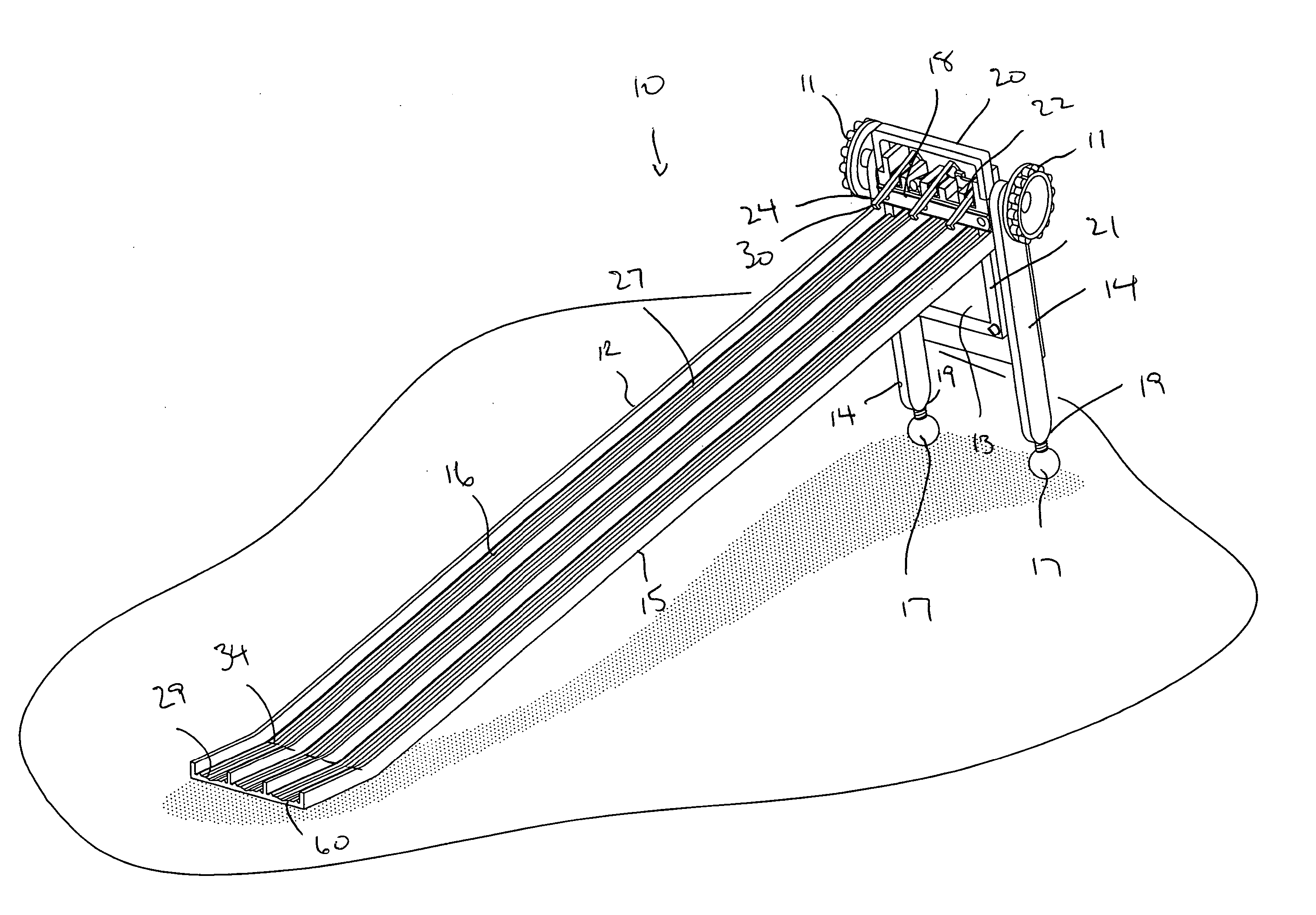
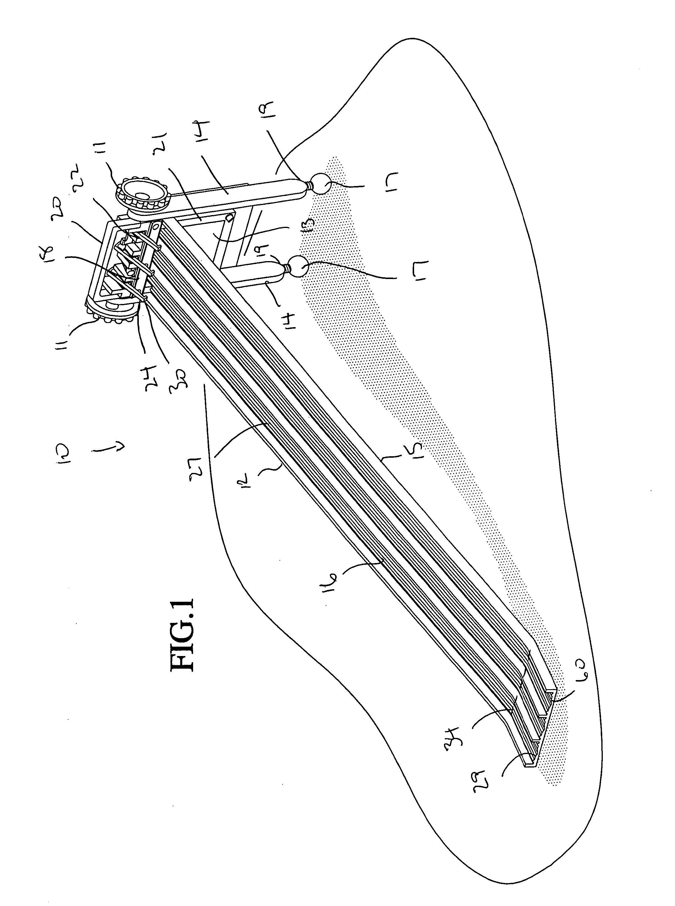
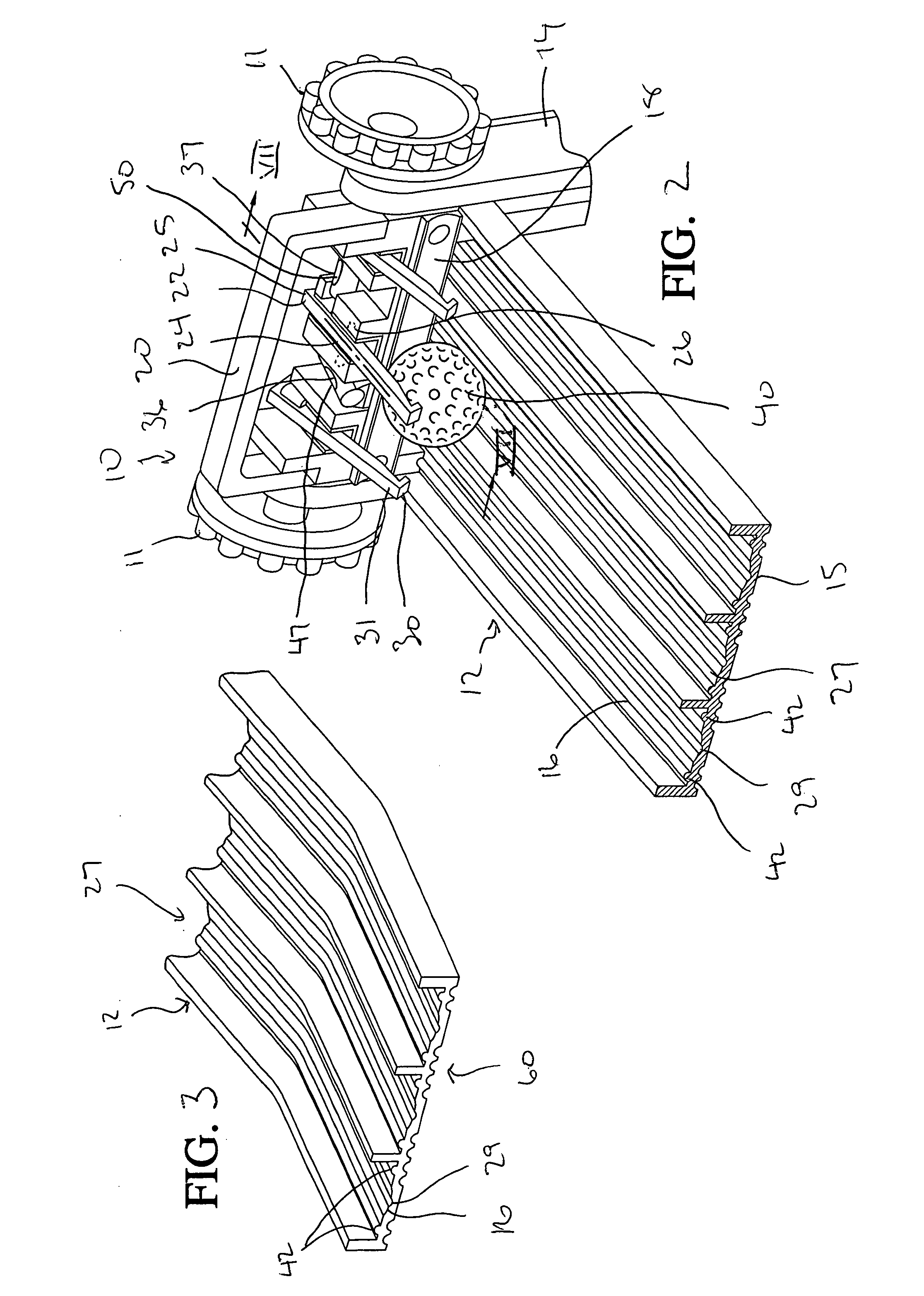
[0037] Referring to FIGS. 1 to 7, the green-speed reading apparatus 10 of the present invention is disclosed. The apparatus 10 is composed of a golf ball rolling ramp 12 supported above a green surface 75 at an angle of 20.2 degrees (in the test position) with a pair of spaced legs 14. The legs 14 are spaced by a cross bar 21 (which in accordance with this embodiment includes a calculator 13 positioned between the spaced legs 14) and are pivotally and removably secured to the ramp 12 by threaded knobs 11.

[0038] The legs 14 pivot when the knobs 11 are loosened s...


PUM

PropertyMeasurementUnit
angleaaaaaaaaaa
angleaaaaaaaaaa
lengthaaaaaaaaaa

Abstract

A method and apparatus is employed in determining the green-speed of a golf putting green. The method is achieved by selecting a site on a putting green having a relatively flat surface and determining the extent of putting surface available for measurements, setting a green-speed reading apparatus including a ramp, which includes a raised start end and a ground contacting release end with at least one golf ball rolling track thereon, in a first direction whereby the release end of the ramp contacts the putting green surface at the selected site, selecting one of two predetermined start positions for a golf ball based upon the extent of putting surface available for measurements and retaining the golf ball at the selected start position in the track, the start position being at the raised start end of the track, releasing the golf ball from the start position, allowing the golf ball to roll down the track by gravity onto the putting green surface, measuring the distance the golf ball rolls across the putting green from the release end of the ramp, repeating the test with the apparatus facing in the opposite direction at the selected site and measuring the distance the golf ball rolls across the putting green from the release end of the ramp, and calculating the average distance of all the golf balls rolled to determine a value in terms of green-speed.

Description

CROSS REFERENCE TO RELATED APPLICATIONS [0001] This application is a continuation-in-part of U.S. patent application Ser. No. 10 / 161,592, entitled “APPARATUS FOR MEASURING GREEN SPEED”, filed Jun. 5, 2002, which is currently pending.BACKGROUND OF THE INVENTION [0002] 1. Field of the Invention [0003] The present invention relates to a method and an apparatus for measuring the “green-speed” of golf course greens. Green-speed more precisely is a measure of distance. It is a quantitative measurement of a green surface characteristic (green-speed), which relates to how far a golf ball rolls after being given a fixed initial speed (e.g. putted from an absolute reference stroke), and then using that quantity for green control, comparison and maintenance purposes. More particularly, the invention relates to an apparatus for measuring the green-speed of putting greens in a precise manner that improves on the current measuring practice. [0004] 2. Description of the Prior Art [0005] The speed ...

Claims


Application Information

Patent Timeline
Patent Type & Authority Applications(United States)
IPC IPC(8): A63B57/00A63B71/02A63B71/06G01N19/02G01N33/00
CPCA63B57/00A63B57/0081A63B71/06A63B2071/025G01N2033/008A63B2220/18A63B2220/20A63B2220/30G01N19/02A63B2220/16A63B57/505A63B71/0605
Inventor PELZ, DAVID T.
Owner PELZ DAVID T
Why Eureka
Try Eureka