Apparatus for applying a reaction force to a pivotally supported pedal member upon depression thereof

Active Publication Date: 2005-07-07
TOYODA IRON WORKS CO LTD
View PDF12 Cites 26 Cited by
  • Summary
  • Abstract
  • Description
  • Claims
  • Application Information

AI Technical Summary

Benefits of technology

[0015] In the pedal reaction force applying apparatus of the first invention, there is provided the reaction-force applying device for applying the pedal reaction force to the pedal member and changing the pedal reaction force. The reaction-force applying device is controlled by the reaction-force controlling device such that the pedal reaction force is changed on the basis of the depressing stroke of the pedal member, according to the predetermined change pattern. Therefore, where the change pattern is adapted to be close to a reaction characteristic of a conventional hydraulically or vacuum boosted braking system, for example, a driver accustomed to the hydraulically or vacuum boosted braking system does not have a strange feeling in depressing the pedal member. That is, it is possible to easily establish a desired reaction characteristic, thereby making possible to improve the pedal maneuverability of a brake-by-wire braking system.
[0016] In the pedal reaction force applying apparatus of the second invention, the spring member is used as the reaction-force applying device, and is connected with the predetermined connected portion of the pedal member that is distant from the support axis. It is therefore possible to apply a large pedal reaction force to the pedal member, easier than in an arrangement in which the reaction-force applying device is disposed in the vicinity of the support axis. Further, the pedal reaction force applying apparatus of the second invention can be constructed easily and inexpensively, since the pedal reaction force can be easily changed by simply displacing the above-described one or other end of the spring member by the reaction-force changing mechanism.
[0017] In the pedal reaction force applying

Problems solved by technology

However, in the above-described conventional pedal reaction force applying apparatus, due to difference between characteristic of a pedal reaction force imparted by a spring member and characteristic of a pedal reaction force imparted by a conventional brake booster, a driver accustomed to a hydraulically or vacuum boosted braking system is likely to

Method used


Image

  • Apparatus for applying a reaction force to a pivotally supported pedal member upon depression thereof
  • Apparatus for applying a reaction force to a pivotally supported pedal member upon depression thereof
  • Apparatus for applying a reaction force to a pivotally supported pedal member upon depression thereof

Examples


embodiment

[0044] There will be described in detail an embodiment of the present invention, with reference to the drawings.

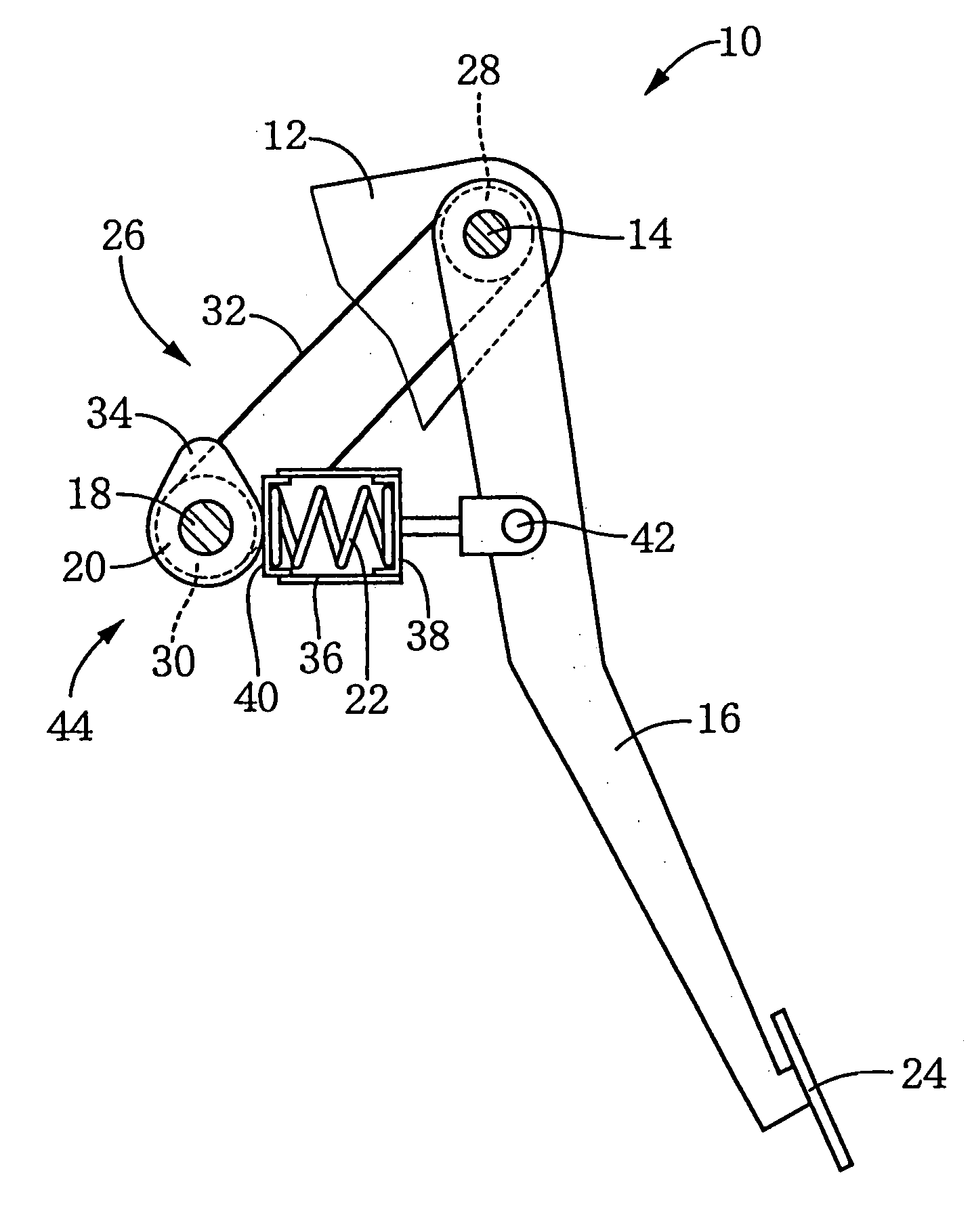
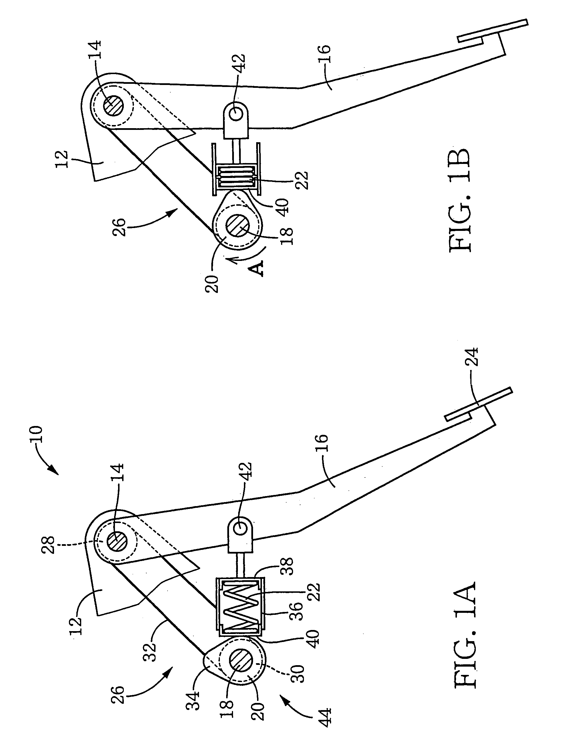
[0045]FIG. 1 is a view showing a pedal reaction force applying apparatus 10 which is one embodiment of the present invention and which is advantageously used in, for example, a brake-by-wire service braking system for a vehicle. This pedal reaction force applying apparatus 10 is equipped with a pedal member 16 disposed pivotably about an axis of a support shaft 14 which is provided in a bracket 12, a cam member 20 disposed pivotably about an axis of a pivot shaft 18 which is provided in the bracket 12 and which is parallel with the support shaft 14, and a compression coil spring 22 interposed between the pedal member 16 and the cam member 20.

[0046] The pedal member 16 is pivotably connected at its upper end portion with the support shaft 14, and is pivoted about the axis of the support shaft 14 in the clockwise direction as a result of an operator's depression operation ...


PUM


Abstract

To provide a pedal reaction force applying apparatus which is easy and inexpensive to manufacture and which is capable of obtaining a pedal reaction force which is close to that of a conventional brake booster.
A compression coil spring 22 is compressively deformed upon depression of a pedal member 16, whereby the pedal reaction force is applied to the pedal member 16. The pedal reaction force can be suitably established depending upon amount of pivot motion of a cam member 20 caused by a transmission mechanism 26 as a result of the depression of the pedal member 16, or depending upon projection amount and projection shape of a lobe portion 34 of the cam member 20. Further, the cam member 20 is mechanically pivoted by the transmission mechanism 26 upon depression of the pedal member 16, and the number of the compression coil spring 22 to be provided in the apparatus may be one. Therefore, the apparatus can be constructed more inexpensively than an apparatus in which a desired reaction characteristic is established by rotating the cam member 20 with an electric motor, or in which a plurality of spring members are used. Further, the apparatus can be compact in construction, and can be installed in the bracket 12 which is located in a front side of a driver's seat, with a high degree of freedom in designing the arrangement of the apparatus.

Description

TECHNICAL FIELD OF INVENTION [0001] The present invention relates to an improvement in a pedal reaction force applying apparatus for applying a pedal reaction force to a pedal member whose depressing stroke is electrically detected so that a hydraulically or otherwise operated brake is activated on the basis of the detected depressing stroke of the pedal member. BACKGROUND ART [0002] There is proposed a brake-by-wire braking system, as a service braking system for a vehicle, in which a depressing stroke (pivot amount) of a pedal member is electrically detected so that an actuator such as a hydraulically operated device and an electrically operated motor is activated on the basis of the detected depressing stroke. In such a braking system, the pedal member receives only very small amount of pedal reaction force which is generated merely by a return spring provided in the pedal member. Therefore, there is a problem that the brake-by-wire braking system is difficult to operate, for a d...

Claims


Application Information

Patent Timeline
IPC IPC(8): B60T8/17B60K26/02B60T7/02B60T7/04B60T7/06B60T8/32G05G1/30G05G1/38G05G1/44G05G5/03
CPCB60T7/042B60T8/3255G05G1/30G05G1/38Y10T74/2101G05G5/03Y10T74/20888Y10T74/20528Y10T74/2107G05G1/44
Inventor FUJIWARA, NOBORU
Owner TOYODA IRON WORKS CO LTD
Why Eureka
Try Eureka