Structure of a uniform thermal conductive heat dissipation device

a heat dissipation device and uniform technology, applied in the direction of semiconductor devices, lighting and heating apparatus, etc., can solve the problems of insufficient heat absorption speed, ineffective heat dissipation of heat dissipation devices, and inability to quickly condensate work fluid to absorb further heat, etc., to achieve uniform thermal conduction and thermal dissipation. uniform

Inactive Publication Date: 2005-07-07
CHAUN CHOUNG TECH
View PDF0 Cites 9 Cited by
  • Summary
  • Abstract
  • Description
  • Claims
  • Application Information

AI Technical Summary

Benefits of technology

[0005] The present invention provides an improved structure of a uniform thermal conductive heat dissipation device, of which heat pipes are embedded in a thermal conductor, and propagation path of heat has been so arranged that the distance between the heat source and each heat pipe is the same. Therefore, a uniform thermal conduction and heat dissipation effect is obtained.

Problems solved by technology

However, due to the limited space within the housing, the conventional heat dissipation device can hardly provide effective heat dissipation.
However, as the heat sink 30a cannot dissipate the heat away efficiently, such heat reflows back to the heat pipes 20a. As a result, the work fluid cannot be condensed quick enough to absorb further heat.
Therefore, the propagation path of heat is too long, and the heat pipes 20 cannot absorb the heat efficiently.

Method used


Image

  • Structure of a uniform thermal conductive heat dissipation device
  • Structure of a uniform thermal conductive heat dissipation device
  • Structure of a uniform thermal conductive heat dissipation device

Examples


Embodiment Construction

[0017] Reference will now be made in detail to the preferred embodiments of the present invention, examples of which are illustrated in the accompanying drawings. Wherever possible, the same reference numbers are used in the drawings and the description to refer to the same or like parts.

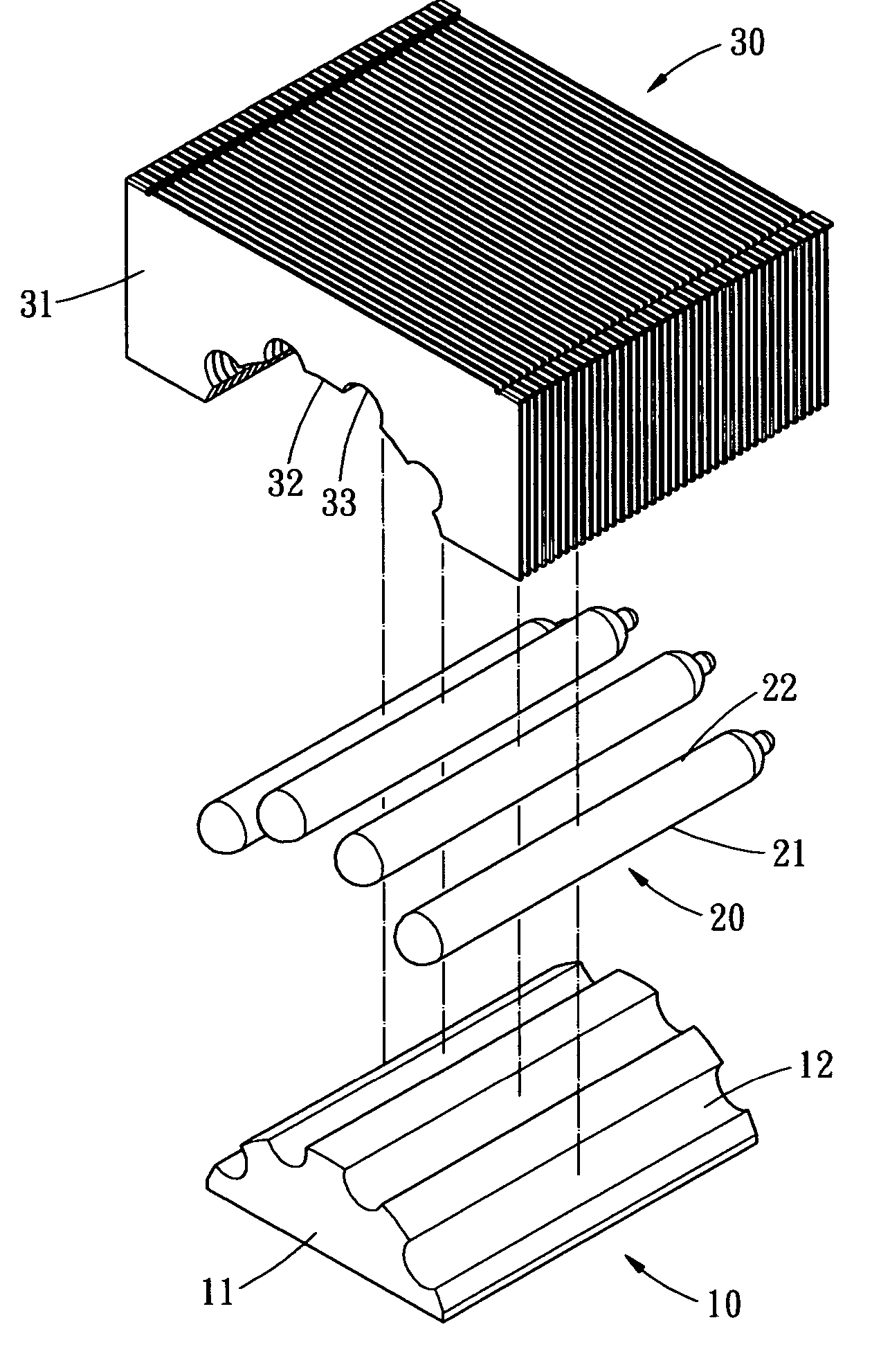
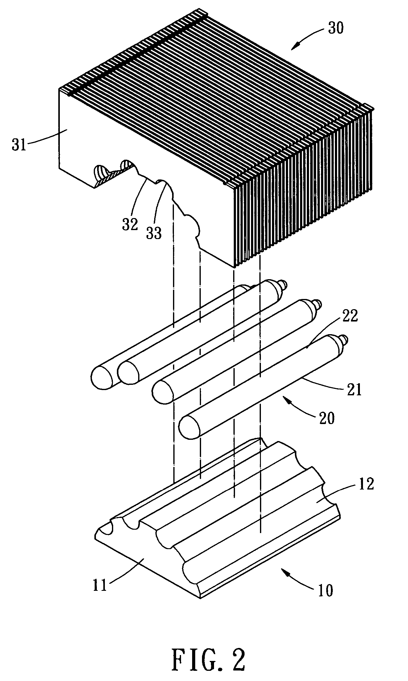
[0018] Referring to FIGS. 2-4, an exploded view, a perspective view, and a cross-sectional view of a first embodiment of a heat dissipation device are illustrated. The heat dissipation device includes a thermal conductor 10 and a plurality of heat pipes 20.

[0019] The thermal conductor 10 is fabricated from material with good thermal conductivity such as copper, for example. The thermal conductor 10 includes a convex body member 11. The convex body member 11 has a semi-circular, trapezium (as shown in FIG. 5), or other geometric cross section. In the current embodiment, the body member 11 has a semi-circular cross section. The curve surface of the body member 11 is processed to form a plurality of ...


PUM


Abstract

An improved structure of a uniform thermal conductive heat dissipation device, having a thermal conductor and a plurality of heat pipes. The thermal conductor includes a convex body member, on which a plurality of parallel connecting parts is formed to allow the heat pipes embedded therein. Each of the heat pipes has a wick structure and a working fluid therein. Each heat pipe has a heat absorbing portion and a heat dissipation portion. The heat absorption portion is closely in contact with the thermal conductor. Thereby, each of the heat is subject to the same amount of heat to result in a uniform thermal conduction and dissipation effect.

Description

BACKGROUND OF THE INVENTION [0001] The present invention relates in general to an improved structure of a uniform thermal conductive heat dissipation device, and more particular, to a heat dissipation device of which the heat pipes are embedded in the thermal conductor to result in uniform thermal conduction and heat dissipation. [0002] In the old computer design, the operation speed of central processing unit (CPU) is so slow that an aluminum extrusion type or fin-type heat sink will be sufficient to dissipate the heat generated by the central processing unit. However, as the clock of central processing unit has exceeded 1 GHz or even reached 3 GHz, the heat generated by the central processing unit increases proportionally to the operation speed. However, due to the limited space within the housing, the conventional heat dissipation device can hardly provide effective heat dissipation. It has thus become a critical problem to be resolved in computer industry. [0003]FIG. 1 shows a c...

Claims


Application Information

Patent Timeline
Patent Type & Authority Applications(United States)
IPC IPC(8): F28D15/02H01L23/427
CPCF28D15/0275F28D2021/0029H01L23/427H01L2924/0002H01L2924/00
Inventor HUANG, MENG-CHENGTSENG, WEN-HAEKANG, JIAN-CHIAN
Owner CHAUN CHOUNG TECH
Why Eureka
Try Eureka