Lawn mower having selectively drivable wheels

a selective drive and lawn mower technology, applied in the direction of non-deflectable wheel steering, transportation and packaging, tractors, etc., can solve the problems of vehicle losing its straight running performance, affecting the smooth turning of the lawn mower, and affecting the smoothness of the turning. , to achieve the effect of excellent straight running performance and smooth turning without marring the ground surfa

Active Publication Date: 2005-07-07
KUBOTA CORP
View PDF13 Cites 21 Cited by
  • Summary
  • Abstract
  • Description
  • Claims
  • Application Information

AI Technical Summary

Benefits of technology

[0011] The object of this invention is to provide a lawn mower having wheels selectively drivable in response to a steering operation, to achieve an excellent straight running performance and to be capable of smooth turning without marring ground surfaces.
[0015] Where the rear wheel clutches are friction clutches, drive transmission to the rear drive wheels may be connected and disconnected smoothly. This will also reduce noise generated in time of clutch operation
[0016] Where the lawn mower has a grass catcher disposed in a rear position of the body frame, and a grass collecting duct for transmitting grass clippings cut by the mower unit rearward to the grass catcher, the grass collecting duct may be disposed to pass between the right axle and the left axle. The change speed device may be disposed laterally the grass collecting duct between the right axle and the left axle. This arrangement clears up the question of space with ease.
[0017] The invention provides also a lawn mower having dirigible front non-drive wheels, and a pair of right and left rear drive wheels. Then, the lawn mower may advantageously comprise a rear wheel differential mechanism with a differential lock function, rear wheel clutches for selectively connecting and disconnecting drive to the respective rear wheels, and an interlocking mechanism for operating the rear wheel differential mechanism and the rear wheel clutches in response to a diplacement to the front wheels from a straight running posture. To realize an excellent straight ruining performance and a turning performance with little chance of marring a ground surface, the interlocking mechanism operates the rear wheel differential mechanism and the rear wheel clutches such that, when the front wheels are at a small steering angle, the rear wheel differential mechanism is unlocked and the rear wheel clutches are both engaged, and when the front wheels are at a large steering angle, the rear wheel differential mechanism is locked and one of the rear wheel clutches associated with one of the rear drive wheels moving along an inner track of turning of the vehicle body is disengaged.

Problems solved by technology

However, where drive is transmitted to drive wheels through a differential mechanism, a difference in rotation between the right and left drive wheels is caused also by loads applied from the ground to the drive wheels in certain surface conditions.
As a result, the vehicle will lose its straight running performance.
This problem is serious for a lawn mower that runs on lawns or meadows in bad ground conditions, compared with an automobile that runs on paved roads.
Further, when a sudden decrease occurs in the load applied from a lawn to one of the rear drive wheels, that rear drive wheel suddenly slips and rotates fast, thereby marring the lawn.
However, even a slight difference in rotation between the right and left rear wheels causes operation of a clutch mechanism.
This reduces durability of the clutch mechanisms, and noise produced by the clutch mechanisms is far from negligible.
Further, a rice planting machine must move with a high straight running performance and sharp turning performance in a paddy field in very difficult surface conditions.
It is difficult to provide a control mechanism for switching drive wheels.
Thus, no mechanism has been employed for operating clutches for right and left rear wheels in response to steering of dirigible wheels.

Method used


Image

  • Lawn mower having selectively drivable wheels
  • Lawn mower having selectively drivable wheels
  • Lawn mower having selectively drivable wheels

Examples


Embodiment Construction

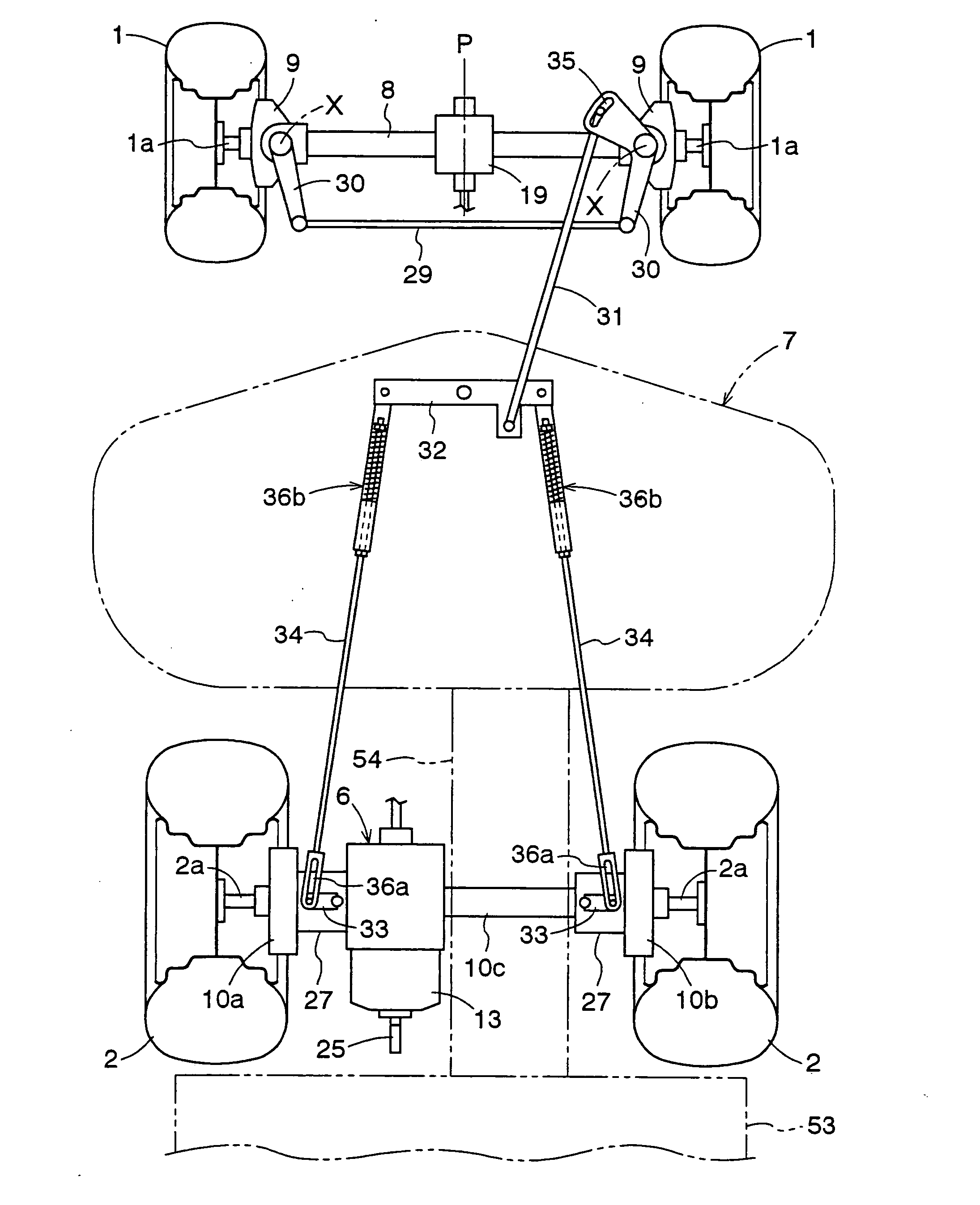
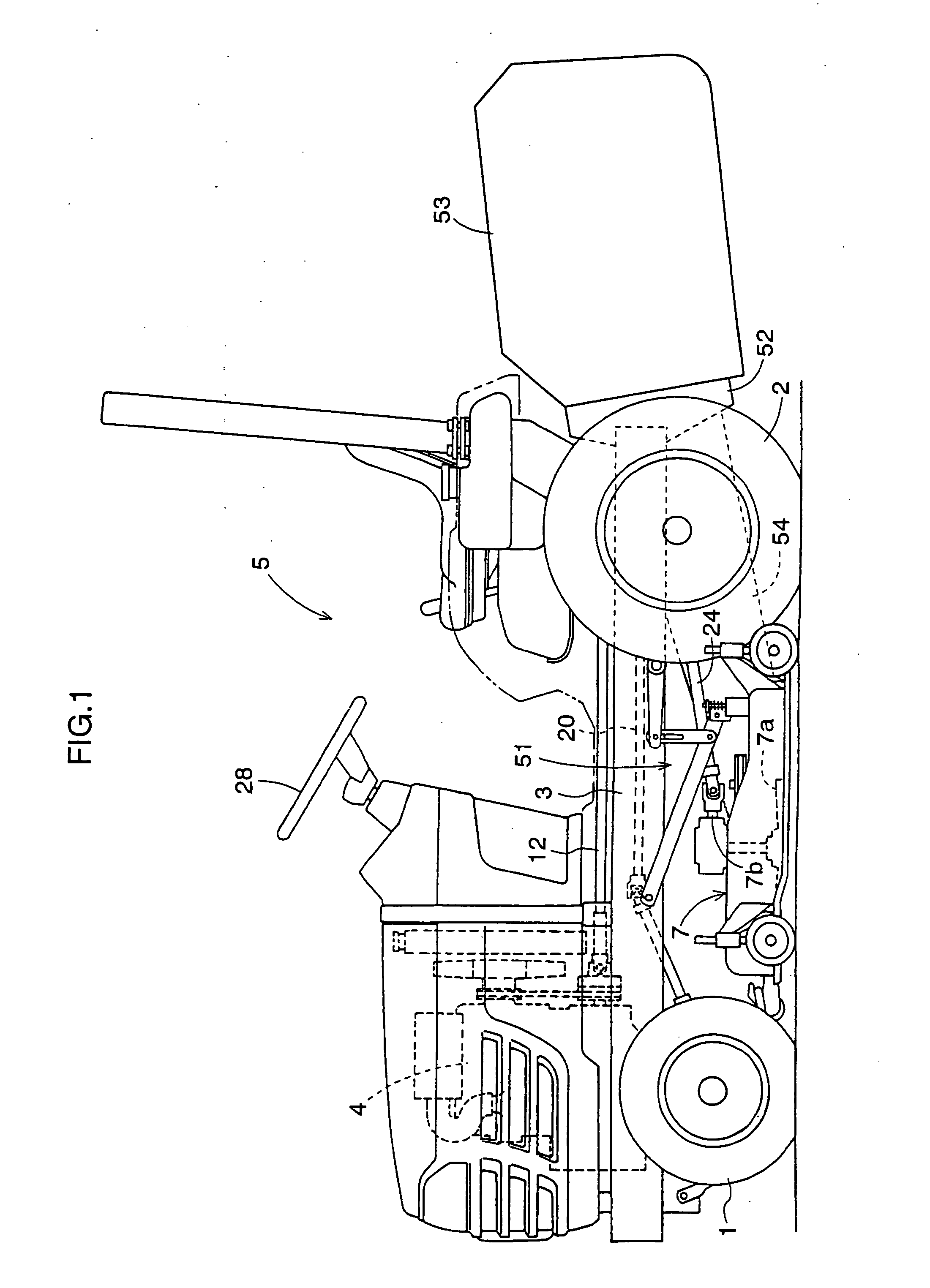
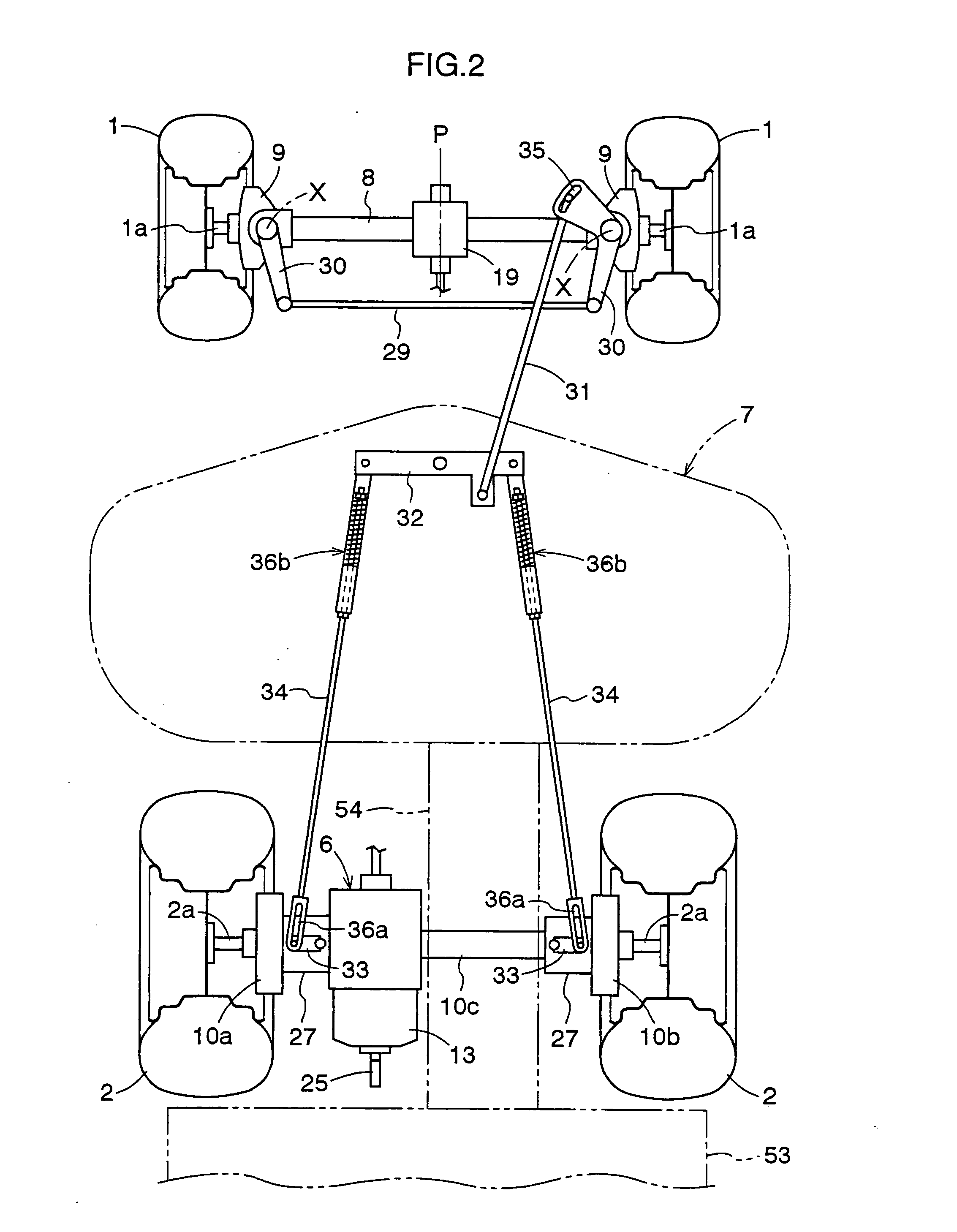
[0029] As shown in FIGS. 1 through 3, a lawn mower according to this invention has a pair of right and left dirigible front drive wheels 1 and a pair of fight and left rear drive wheels 2 supporting a body frame 3. An engine 4 is mounted on a front portion of the body frame 3, and a driving platform 5 is formed on an upper rear portion of the body frame 3. Below the driving platform 5 is a transmission case 6 housing a change speed device including a gear transmission mechanism 6a and a stepless transmission 13 (which is an HST here). A mower unit 7 is vertically movably attached to the body frame 3 through a lift mechanism 51 in a space between the front drive wheels 1 and rear drive wheels 2. The mower unit 7 is the rear discharge type having a plurality of blades 7a juxtaposed transversely of the body frame 3 for cutting grass and rearwardly discharging grass clippings. In this embodiment, a grass catcher 53 is attached to the rear end of the body frame 3 through a bracket 52. A ...


PUM


Abstract

A lawn mower having selectively drivable wheels, includes dirigible front drive wheels, a pair of right and left rear drive wheels, a body frame, an engine supported by the body frame, a mower unit vertically movably supported by the body frame forwardly of the rear drive wheels, a change speed device for changing a speed of drive from the engine, a front wheel driving device for transmitting drive from the change speed device to the front wheels, a left rear wheel driving device for transmitting drive from the change speed device to a right axle of the left rear wheel, a right rear wheel driving device for transmitting drive from the change speed device to a left axle of the left rear wheel, and rear wheel clutches associated with the left rear wheel driving device and the right rear wheel driving device, respectively, for selectively connecting and disconnecting drive. The rear wheel clutches are operable by an interlocking mechanism in response to a displacement to the front drive wheels from a straight running posture, to disconnect drive transmission to one of the rear drive wheels moving along an inner track of turning of the vehicle body. The interlocking mechanism has a link mechanism operatively connecting a steering mechanism for steering the front drive wheels to each of the rear wheel clutches, and extending over the mower unit.

Description

BACKGROUND OF THE INVENTION [0001] 1. Field of the Invention [0002] This invention relates to a lawn mower having selectively drivable wheels. [0003] 2. Description of the Related Art [0004] A conventional lawn mower has freely rotatable dirigible front wheels, and rear drive wheels. A rear wheel differential mechanism is disposed on a drive transmission line from the engine to the rear wheels. When making a turn, the right and left rear drive wheels are driven at different speeds. Another type of lawn mower has dirigible front drive wheels, and rear drive wheels. A front wheel differential mechanism is disposed on a drive transmission line from the engine to the front wheels, while a rear wheel differential mechanism is disposed on a drive transmission line from the engine to the rear wheels. When making a turn, the right and left front and rear drive wheels are driven at different speeds through the two differential mechanisms. [0005] A differential mechanism can absorb a differen...

Claims


Application Information

Patent Timeline
Patent Type & Authority Applications(United States)
IPC IPC(8): A01D34/64A01D34/66A01D34/69B62D11/08B62D49/00
CPCA01D34/64A01D2101/00A01D34/69A01D34/66
Inventor ISHIMORI, SHOSO
Owner KUBOTA CORP
Why Eureka
Try Eureka