Stepping motor drive device and method

a technology of stepping motor and drive device, which is applied in the direction of motor/generator/converter stopper, dynamo-electric converter control, electric controller, etc., can solve the problems of slow attenuation of coil current at the time of the staircase signal decrease, poor follow-up of coil current of the staircase signal, and degradation of the recorded image, etc., to achieve rapid rate, adequate reduction of vibration and noise, and enhanced power supply

Active Publication Date: 2005-07-07
COLLABO INNOVATIONS INC
View PDF2 Cites 9 Cited by
  • Summary
  • Abstract
  • Description
  • Claims
  • Application Information

AI Technical Summary

Benefits of technology

[0025] In a stepping motor drive device with the above configurations, the supply current is controlled to a target value represented by the reference signal whose signal level changes continuously over time. Hence, compared to the prior art in which the target value for the current supply control is represented by a staircase signal, vibration and noise, induced by torque fluctuations at a time of stepwise increase and decrease in the target value, are eliminated.
[0026] Furthermore, in order to achieve an adequate reduction in vibration and noise, the coil current is controlled according to a limit value for the supply current represented by, for instance, an approximate sinusoidal staircase signal. In this case, by prohibiting the synchronous rectification, the coil current is brought to decay rapidly during a period when the reference signal is decreasing at a relatively rapid rate. Herewith, the coil current follows the limit value closely. In the time other than the above period, on the other hand, the power supply efficiency is enhanced by carrying out the synchronous rectification and thereby mitigating decay of the coil current.
[0027] Thus, providing implementation and prohibition periods of the synchronous rectification according to the decreasing rate of the reference signal allows to achieve a reduction in vibration and noise as well as a good efficiency in the power supply.
[0028] In addition, the stepping motor drive device of the present invention exercises a PWM control on the supply current supplied to the coil, using a current chopper method. This achieves lower power operation compared to the case where the current is supplied to the coil by voltage control.
[0029] Here, the integration circuit may generate the reference signal which follows an average gradient of the staircase signal by integrating the staircase signal using a time constant corresponding to a rate of change in levels of the staircase signal.
[0030] Here, the integration circuit may acquire a change rate signal indicating the rate of change in the levels of the staircase signal, and determine the time constant according to the change rate signal.

Problems solved by technology

This is because sounds generated by a stepping motor are caught by a built-in microphone of the electronics device and recorded as noise, while vibrations generated by a stepping motor cause image blurring and result in degradation of the recorded image.
However, as to the drive device of the related art above, the attenuation of the coil current at the time when the staircase signal is decreasing is slow, and therefore the coil current poorly follows the staircase signal.
As a result, this presents the first problem that an intended reduction in vibration and noise cannot be obtained.
This is a serious problem particularly when the stepping motor is applied to image capturing electronics devices, and thus there is still a demand for further reduction in noise and vibration of the stepping motor operations.
In addition, there is a second problem that the drive device of the above related art requires a considerable amount of power since the coil current is continuously supplied.

Method used


Image

  • Stepping motor drive device and method
  • Stepping motor drive device and method
  • Stepping motor drive device and method

Examples


first embodiment

1. First Embodiment

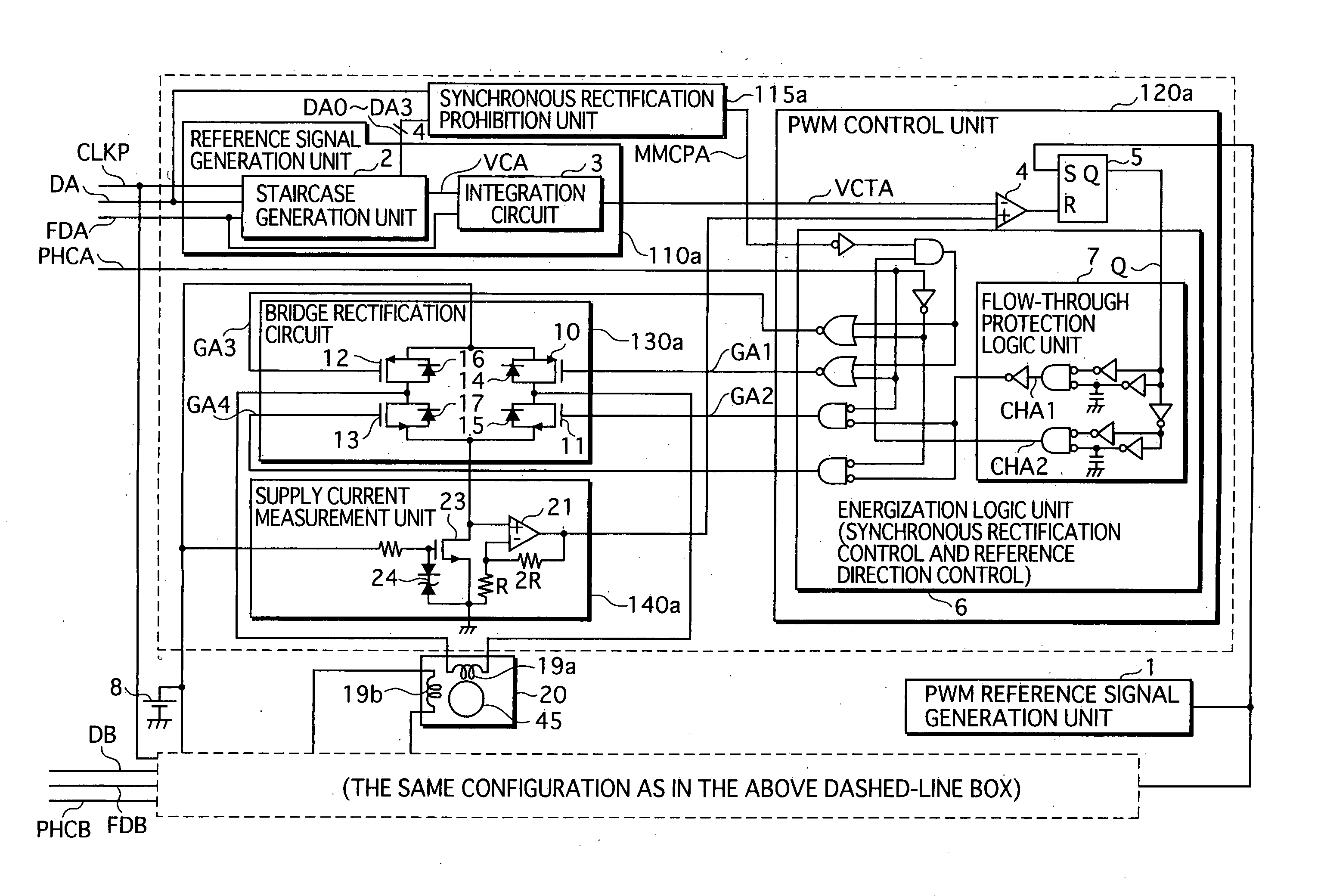
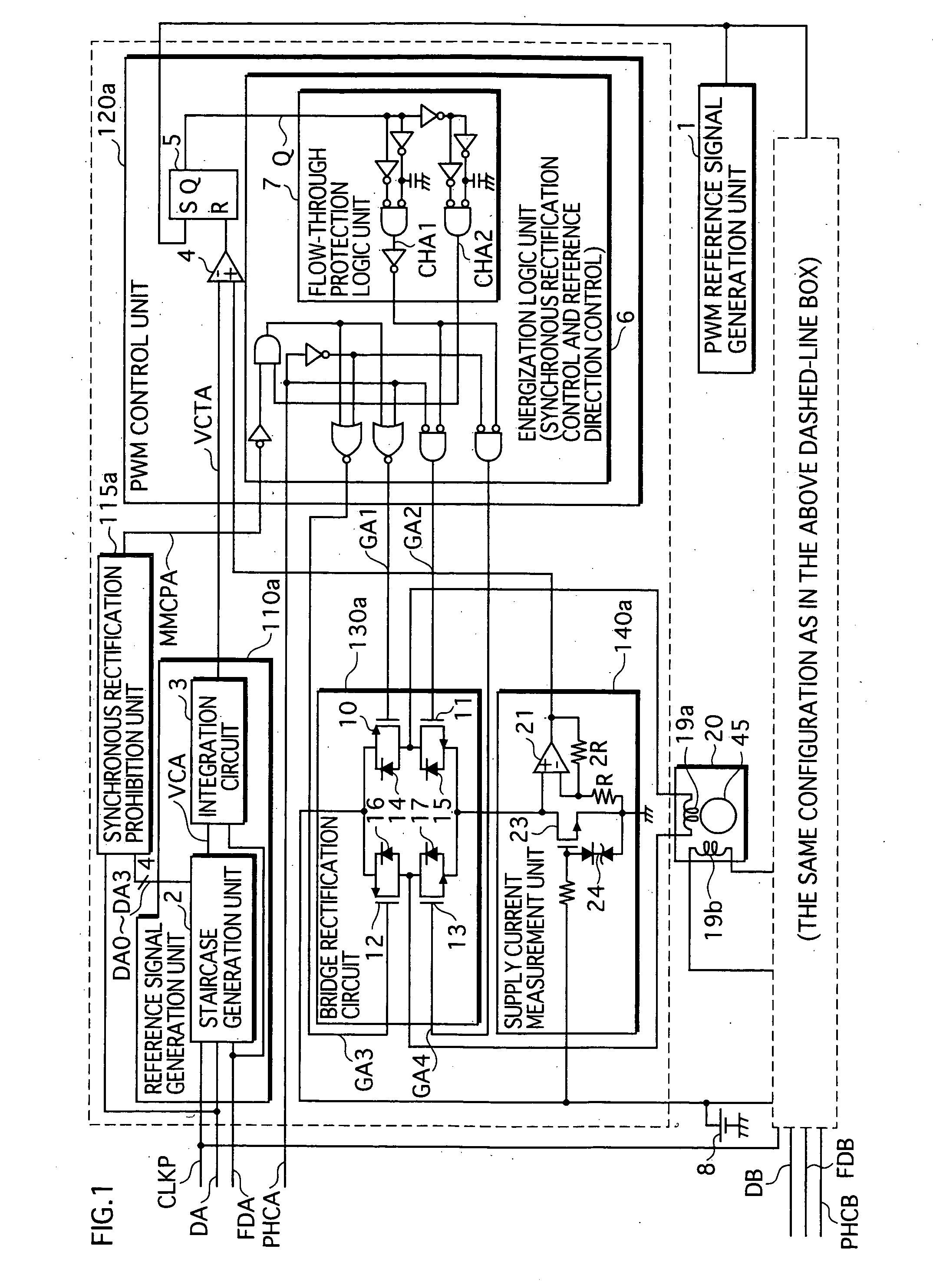
[0083] A stepping motor drive device of the first embodiment of the present invention generates a reference signal whose signal level changes continuously over time. The level of the reference signal represents a limit value for the supply current. Here, ‘a signal whose level changes continuously over time’ means that the signal does not have abrupt, stepwise changes in the signal level. Examples of such signals are a sine wave signal, a triangular wave signal whose rises and falls are inclined, and a trapezoidal wave signal.

[0084] The stepping motor drive device exercises PWM (Pulse Width Modulation) control on a current supplied to the motor coil, according to the limit value represented by the generated reference signal. More specifically, the PWM control is executed using a current chopper method.

[0085] In addition, the stepping motor drive device implements synchronous rectification. In this rectification process, a switch for the synchronous rectification ...

second embodiment

2. Second Embodiment

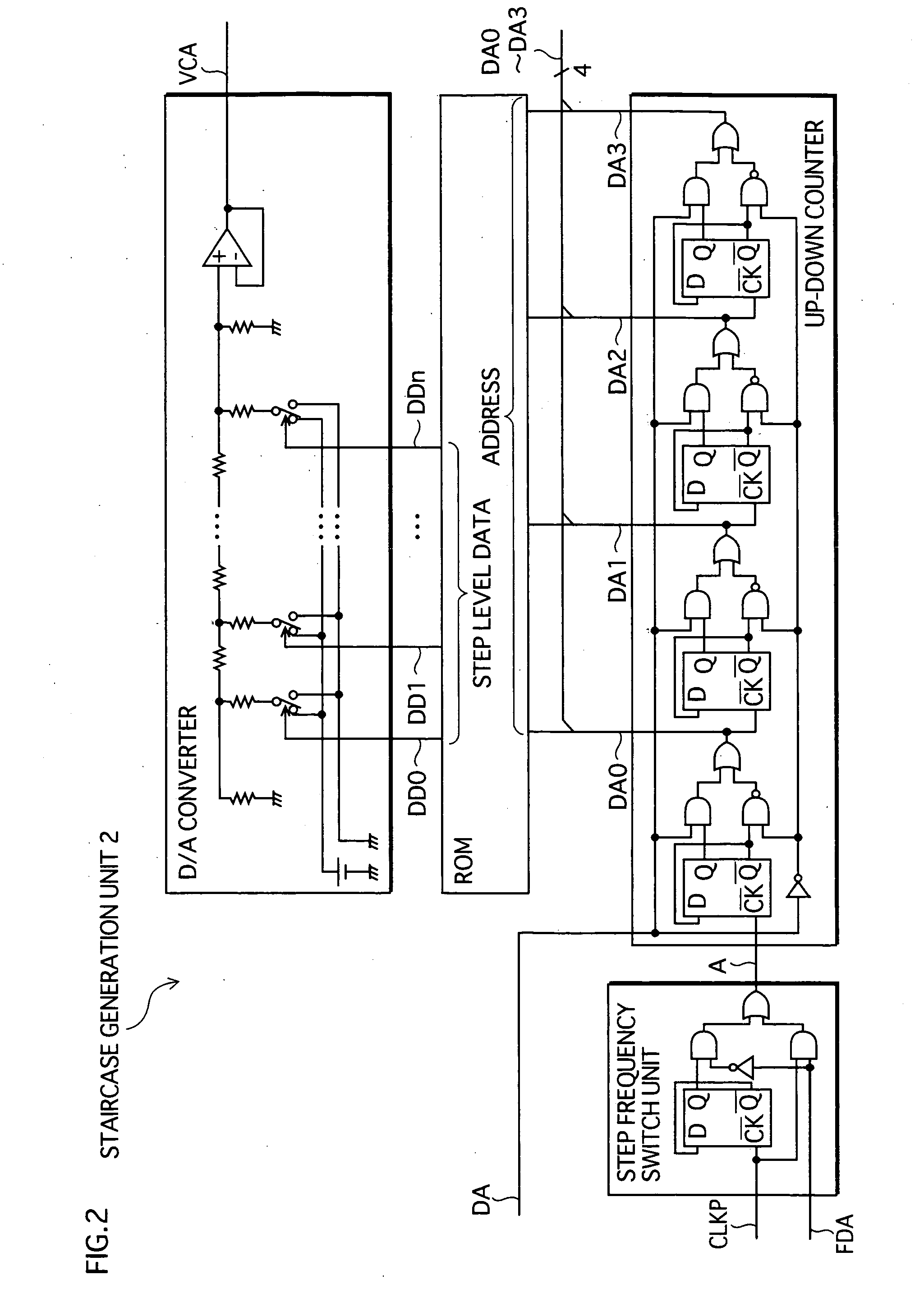
[0150] A stepping motor drive device of the second embodiment of the present invention differs from the first embodiment in the way of generating the reference signal. According to the second embodiment, the above-mentioned change rate signal is generated within the device by discriminating a pulse frequency of the clock signal. Then, using the change rate signal, the reference signal is generated. The following mainly describes the differences of the second embodiment from the first embodiment.

[0151] 2.1 Configuration of Major Components Relevant to Reference Signal Generation

[0152]FIG. 13 is a functional block diagram showing a configuration relevant to the reference signal generation in the second embodiment. Compared to the first embodiment, a pulse frequency discrimination unit 22 is added. In the first embodiment, the change rate signal FDA is provided from outside. However, in the second embodiment, the pulse frequency discrimination unit 22 generates th...

third embodiment

3. Third Embodiment

[0162] A stepping motor drive device of the third embodiment of the present invention differs from the second embodiment in the configuration relevant to the reference signal VCTA generation. The following mainly describes the differences of the third embodiment from the second embodiment.

[0163] 3.1 Configuration of Major Components Relating to Reference Signal Generation

[0164]FIG. 16 is a functional block diagram showing a configuration relevant to the reference signal generation in the third embodiment. Compared to the second embodiment, an integration circuit 25 is used, instead of the integration circuit 3.

[0165] 3.2 Integration Circuit 25

[0166] The integration circuit 25 includes switches controlled by both a change rate signal FDA and a program signal PRG so as to adjust resistance that determines a time constant.

[0167]FIG. 17 is a functional block diagram showing a detailed configuration of the integration circuit 25. In order to choose an appropriate t...


PUM


Abstract

The reference signal generation unit 110a integrates, in the integration circuit 3, a staircase signal generated by the staircase generation unit 2, and thereby generates a reference signal VCTA whose signal level changes continuously over time, and which represents a limit value for the supply current. According to the control of the PWM control unit 120a, the bridge rectification circuit 130a maintains the coil supply current at the limit value, using a current chopper method. Additionally, when the current supply is stopped, the bridge rectification circuit 130a performs synchronous rectification, where the transistors 10 and 12 are brought into conduction, and a regenerative current is circulated in a closed circuit formed with the coil 19a. When the reference signal VCTA decreases relatively fast, the synchronous rectification prohibition unit 115a prohibits one of the transistors 10 and 12 from being brought into conduction when the current supply is stopped.

Description

BACKGROUND OF THE INVENTION [0001] [1] Field of the Invention [0002] The present invention relates to a stepping motor drive device, in particular to a technology for driving a stepping motor with low noise and low vibration. [0003] [2] Description of the Related Art [0004] Late years, stepping motors are used in image capturing electronics devices, such as a DSC (Digital Still Camera) and a DVC (Digital Video Camera), as optical system actuators for adjusting aperture, focus, zoom and so on. [0005] Stepping motors, especially those used for image capturing electronics devices, are required to operate with low noise and low vibration. This is because sounds generated by a stepping motor are caught by a built-in microphone of the electronics device and recorded as noise, while vibrations generated by a stepping motor cause image blurring and result in degradation of the recorded image. [0006] In response to such a demand, a drive technology for stepping motor operations with low nois...

Claims


Application Information

Patent Timeline
Patent Type & Authority Applications(United States)
IPC IPC(8): H02P8/10H02P8/00H02P8/12H02P8/22H02P8/32
CPCH02P8/32H02P8/12H02P21/00
Inventor FUKAMIZU, SHINGOONISHI, KATSUHIRO
Owner COLLABO INNOVATIONS INC
Why Eureka
Try Eureka