Microstrip antenna

Inactive Publication Date: 2005-07-07
YOKOWO CO LTD
View PDF5 Cites 17 Cited by
  • Summary
  • Abstract
  • Description
  • Claims
  • Application Information

AI Technical Summary

Benefits of technology

[0009] It is therefore an object of the invention to provide a microstrip antenna which

Problems solved by technology

Under the circumstances, there is such an anxiety that a desired di

Method used


Image

  • Microstrip antenna
  • Microstrip antenna
  • Microstrip antenna

Examples


Example

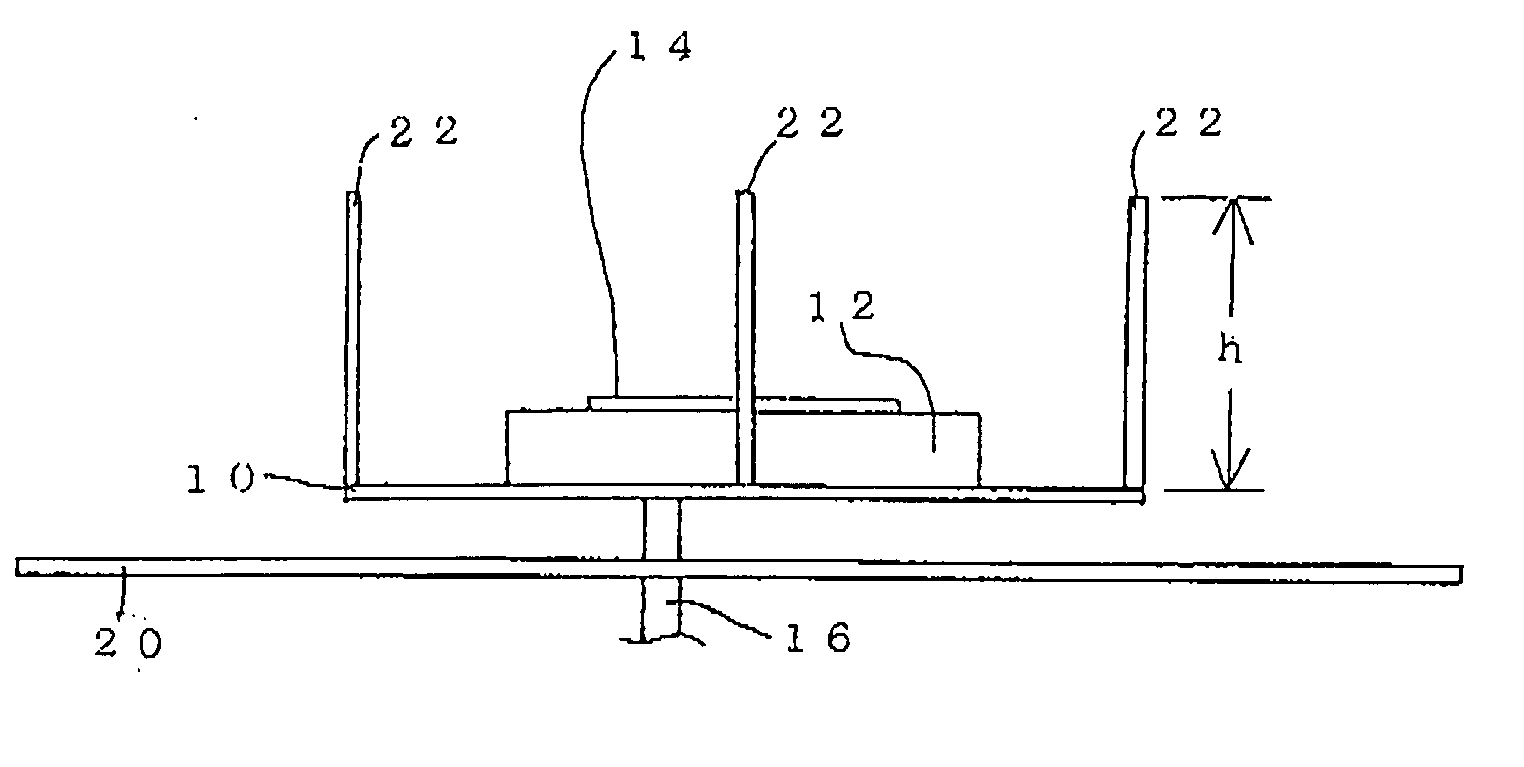
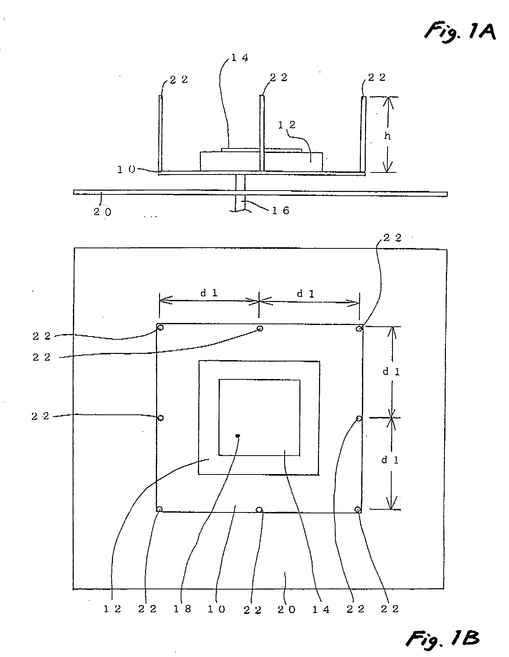
[0031] In the microstrip antenna according to a first embodiment of the invention, as shown in FIG. 1, the microstrip antenna is different from the structure as shown in FIG. 6 in that a plurality of metal rods 22 are uprightly provided on edges of the ground 10 at a side where the patch antenna element 14 is mounted. A base end of each of the metal rods 22 is electrically connected to the ground 10. A height h of the metal rod 22 is set to have an electric length of ¼ of a wavelength λ of resonant frequency of the microstrip antenna. A distance d1 between the respective metal rods 22 is set to have an electric length less than ½ of the wavelength λ. The metal rods 22 must be uprightly provided in the four corners of the ground 10, and in a case where the distance between these metal rods 22 has an electric length longer than λ / 2, the metal rod 22 may be additionally provided between them on the edge of the ground 10.

[0032] According to this structure, standing waves of the resonan...

Example

[0035] Next, a second embodiment of the invention will be described referring to FIGS. 3A and 3B. In this embodiment, similar members to those shown in FIG. 1 will be denoted with the same reference numerals, and repetitive description will be omitted.

[0036] In this embodiment, a ground 30 has a circular shape in a plan view. The metal rods 22 are equidistantly provided uprightly on an edge of the ground 30 in such a manner that a distance d2 between the respective metal rods 22 may have an electrical length less than λ / 2. As the results, in the same manner as with the structure in the first embodiment, the coupling to the metallic conductor 20 in the surroundings is decreased, and the directivity having a high gain in an upward direction can be obtained.

[0037] It is easily understood that in the above described embodiments, the height h of the metal rod 22 is not limited to λ / 4, but may be an odd multiple of λ / 4, for example, 3λ / 4 or 5λ / 4, provided that the height may be so set a...


PUM


Abstract

In a microstrip antenna, a dielectric member is disposed on a grounded conductive plate. A patch antenna element is disposed on the dielectric member. Each of a plurality of conductive rods has an electrical length corresponding to one quarter of a wavelength at a resonance frequency of the microstrip antenna. The rods are arranged on an edge portion of a face of the conductive plate facing the patch antenna element, with an interval which is an electric length corresponding to a half or less of the wavelength at the resonance frequency, such that each of the rods extends perpendicularly to the conductive plate while one end thereof is electrically connected to the conductive plate.

Description

BACKGROUND OF THE INVENTION [0001] The present invention relates to a microstrip antenna having a planar patch antenna element. [0002] An example of a related-art microstrip antenna will be described referring to FIGS. 4A to 5. [0003] As shown in FIGS. 4A and 4B, a dielectric substrate 12 is placed on an upper face of a ground 10 formed of conductive metal, and a planar patch antenna element 14 is placed on an upper face of this dielectric substrate 12. Passing through the ground 10 and the dielectric substrate 12, a core conductor of a feeding cable 16 is electrically connected to the patch antenna element 14. A feeding point 18 of the patch antenna element 14 is at a position offset from a center of the patch antenna element 14. [0004] For the directivity of the microstrip antenna having the above described structure, a high gain can be obtained in an upward direction, and a half power width can be narrowed, as shown in FIG. 5. [0005] In a case where the above described microstrip...

Claims


Application Information

Patent Timeline
IPC IPC(8): H01Q1/32H01Q3/44H01Q1/38H01Q1/52H01Q9/04H01Q13/08H01Q19/28
CPCH01Q1/3233H01Q1/3291H01Q19/28H01Q9/0407H01Q1/528
Inventor SAMPO, TAKESHI
Owner YOKOWO CO LTD
Why Eureka
Try Eureka