
Digital camera system, image storage apparatus, and digital camera

a digital camera and image processing technology, applied in the field of digital camera systems, image storage apparatuses, digital cameras, can solve the problems of high cost of applying digital camera technology, large storage medium costs incurred by users, and high cost of applying image processing technology to which much research effort has been directed in pursuit of better quality images, etc., and achieve the effect of low cos

Inactive Publication Date: 2005-07-07
NIKON CORP
View PDF25 Cites 117 Cited by
  • Summary
  • Abstract
  • Description
  • Claims
  • Application Information

AI Technical Summary

Benefits of technology

[0017] A first object of the present invention is to provide a high-performance digital camera at low cost by addressing the problems of related art 1 discussed above.

Problems solved by technology

This has lead to greater storage medium costs incurred by the user.
While significant progress has been made in the area of the image compression technology adopted to ensure the required storage capacity, the cost of applying the technology in digital cameras has been high.
At the same time, the cost of applying the image processing technology to which much research effort has been directed in pursuit of better quality images, too, is high.
However, there are still numerous technical challenges, such as reducing the volume of the data to be transmitted, that need to be met before the technology can be effectively adopted in practical application.
At the same time, the use of such a digital camera back is limited to special cases in which a user wishes to utilize a high-grade single lens reflex camera body and the performance of its set of interchangeable lenses, for instance.
However, if the user fails to input image information to the means for management from the digital camera, the image information is likely to become lost instead of being taken under the management of the means for management.
In addition, while each storage medium taken out of the digital camera may be stored in a well-organized manner, there is still the risk of the user becoming confused as to exactly where the individual images are stored as the number of storage media increases.

Method used


Image

  • Digital camera system, image storage apparatus, and digital camera
  • Digital camera system, image storage apparatus, and digital camera
  • Digital camera system, image storage apparatus, and digital camera

Examples


first embodiment

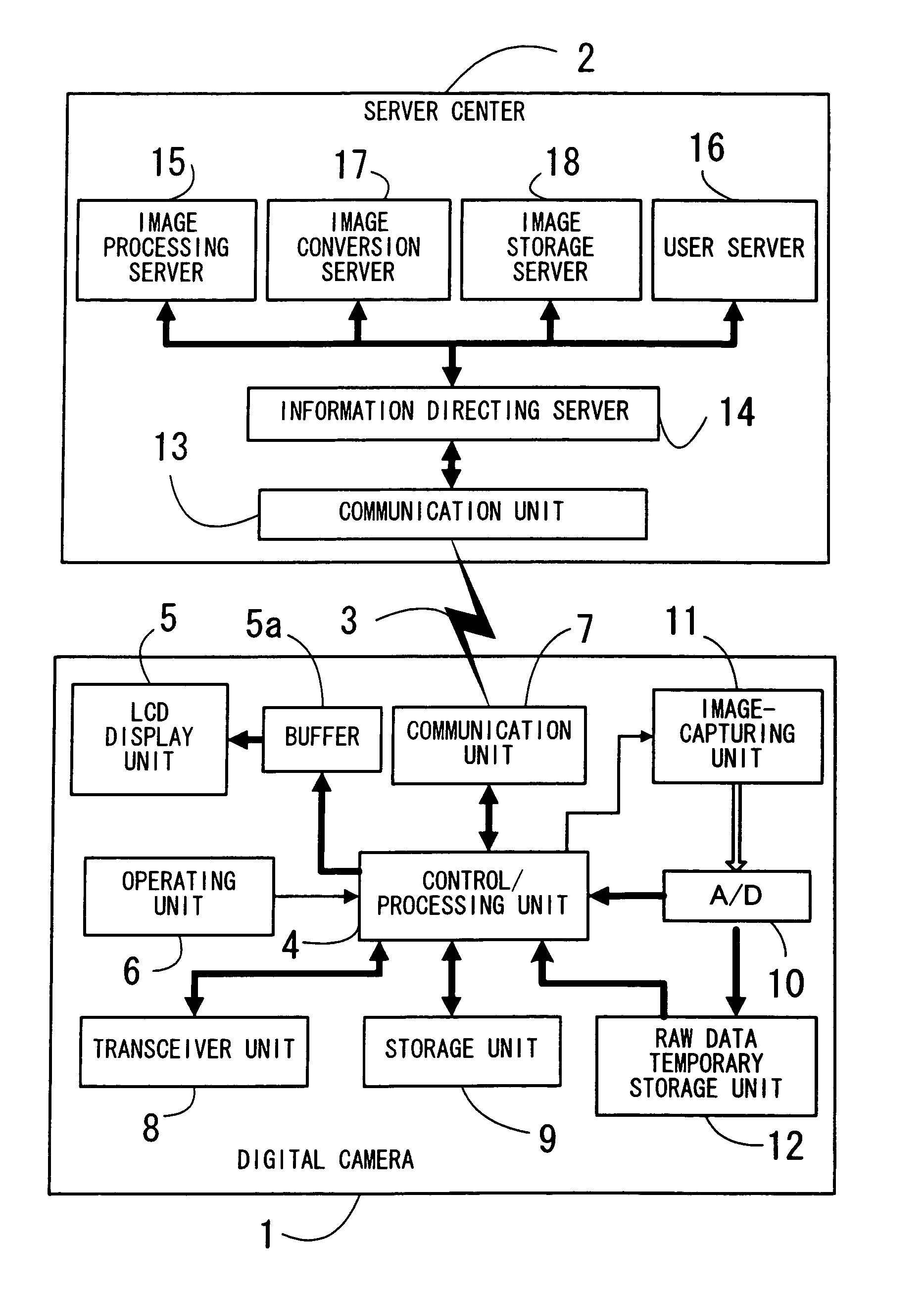
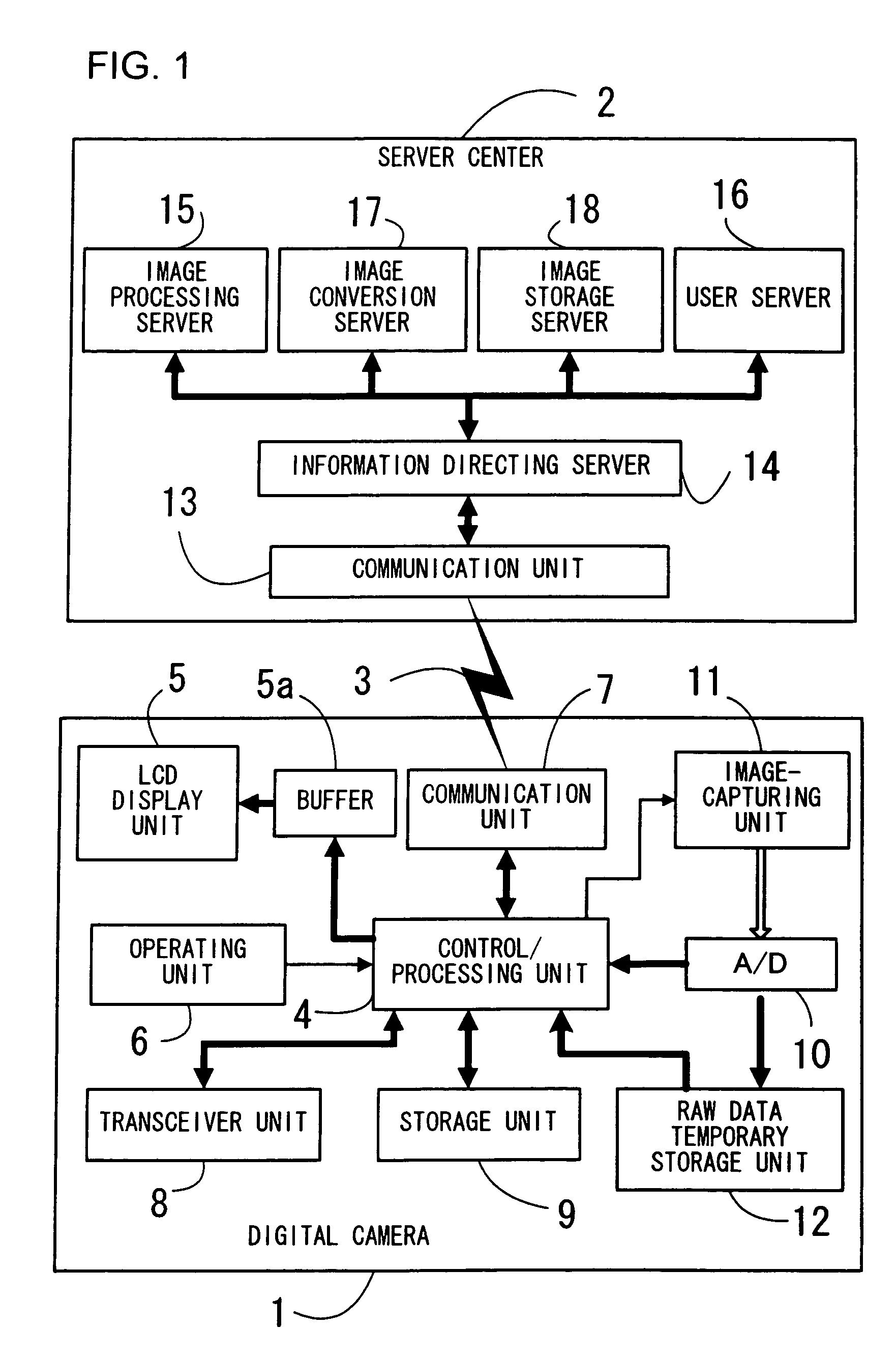
[0125]FIG. 1 is a block diagram of a digital camera system achieved in the first embodiment of the present invention. A digital camera, which is realized as a digital camera integrated portable telephone 1, is built into the portable telephone (cellular phone) as an integrated part thereof. The essential functions of the digital camera are provided at a server center 2 which functions as an image storage apparatus, and as the digital camera integrated portable telephone 1 and the server center 2 work together through a wireless communication 3 achieved via the Internet or the like by utilizing a public communication line, the functions of the digital camera are fulfilled. In more specific terms, the wireless communication 3 may be executed so as to establish a connection with the server center 2 via the Internet by first connecting to a provider from a portable telephone line, to establish the connection with the server center 2 via the Internet by first connecting to a provider's L...

second embodiment

[0216]FIG. 16 is a block diagram of the second embodiment of the present invention, having the same reference numerals assigned to components identical to those in the first embodiment shown in FIG. 1. In the second embodiment shown in FIG. 16, the present invention is adopted in a digital camera back 42 to be mounted at a silver halide film camera 41 instead of in a digital camera integrated portable telephone. It shares similarities with the first embodiment in that some of the digital camera functions are provided at the server center 2 and that the digital camera back 42 and the server center 2 work together through a wireless communication 3. It is to be noted that the specific structure adopted by the server center 2 shown in FIG. 16 is identical to that in FIG. 1.

[0217] While the silver halide film camera 41 adopts a standard structure, the digital camera back 42 is mounted in place of its detachable rear lid. As a result, a photographic optical system 43 forms a subject ima...

third embodiment

[0225] In the block diagram of the third embodiment according to the present invention presented in FIG. 16, the same reference numerals are assigned to components identical to those in the second embodiment shown in FIG. 16. In the third embodiment shown in FIG. 17, which adopts a structure basically identical to that of the second embodiment in FIG. 17, the structure of a digital camera back 61 is further simplified by using the communication function of a regular portable telephone 60. The third embodiment shares similarities with the first embodiment and the second embodiment in that some of the digital camera functions are fulfilled at the server center 2 and that the digital camera back 61 works together with the server center 2 through a wireless communication 3. It is to be noted that the specific structure adopted in the server center 2 shown in FIG. 17 is identical to that shown in FIG. 1, whereas the specific structure of the silver halide film camera 41 is identical to t...


PUM


Abstract

A digital camera system includes: a digital camera 1 that wirelessly transmits raw data from an image capturing unit 11 and information of the image capturing unit 11; and a server center 2 that receives them via Internet and executes interpolation, white balance adjustment, edge emphasis, subsampling and compression with them. The digital camera 1 generates thumbnail images or small size reproduction images by subsampling the identical raw data and stores them in relation to the raw data which have been transmitted. The digital camera 1 is constituted as a portable telephone integrated digital camera, and the transmission of image and the storage and the display of post-subsampling data are achieved by utilizing the standard functions of the portable telephone.

Description

TECHNICAL FIELD [0001] The present invention relates to a technology for transmitting a digital image generated with a digital camera to an outside recipient, a technology for storing the digital image externally and a technology for reproducing the digital image. BACKGROUND ART [0002] -Related Art 1- [0003] As the number of pixels created in digital cameras has become increasingly large in recent years, greater storage capacity must be assured to store images generated with such digital cameras. This has lead to greater storage medium costs incurred by the user. While significant progress has been made in the area of the image compression technology adopted to ensure the required storage capacity, the cost of applying the technology in digital cameras has been high. At the same time, the cost of applying the image processing technology to which much research effort has been directed in pursuit of better quality images, too, is high. [0004] Yet another factor that is keeping the pro...

Claims


Application Information

Patent Timeline
IPC IPC(8): H04N1/00H04N1/21H04N7/14
CPCH04N1/00127H04N2201/3288H04N1/00137H04N1/00151H04N1/00167H04N1/00172H04N1/00196H04N1/00307H04N1/2166H04N1/2187H04N1/2195H04N1/32122H04N7/147H04N2007/145H04N2101/00H04N2201/001H04N2201/325H04N1/00132
Inventor TANAKA, MASAHIDEOHMURA, AKIRAOHTA, TADASHI
Owner NIKON CORP
Learn More