Image encodder, image decoder, record medium, and image recorder

a technology of image encoder and image, which is applied in the field of image encoder, image encoder, recording medium and image recording apparatus, can solve the problems of low coding efficiency, large dct coefficient high-frequency components, and low coding efficiency, so as to facilitate post-recording modification, facilitate handling, and facilitate the effect of recording

Inactive Publication Date: 2005-07-07
SHARP KK
View PDF5 Cites 42 Cited by
  • Summary
  • Abstract
  • Description
  • Claims
  • Application Information

AI Technical Summary

Benefits of technology

[0037] According to the image coding apparatus of the present invention, since, for encoding of a stereo image after joining, the joining and encoding of images is performed so as to enhance the continuity of the joined image at the boundary, it is possible to achieve efficient coding. Further, images to be joined are input in parallel and subjected to joining and coding processes, whereby it is possible to reduce the delay of the coding process.
[0049] According to the image recording apparatus of the present invention, since the joining method information and the information of generating a 2-dimetnsional display image are recorded into the subcode sector in the recording area, the subcode recording sector can be recorded by post-recording, hence can be modified easily.

Problems solved by technology

Therefore, there is a problem in that the coding efficiency lowers when JPEG or other coding is carried out.
For example, if the boundary between the left and right images exists in a DCT block of JPEG, the high-frequency components of DCT coefficients become large, hence the coding efficiency lowers.
Moreover, in the case of MPEG-4, even if no boundaries reside within a DCT block, there may occur a case where the coding efficiency lowers.
Since the DCT coefficient of the left image is generally discontinuous from that of the right image around the boundary, prediction of DCT coefficients yields poor results, hence the coding efficiency lowers.
On the other hand, when a joined image for stereo display is output on a 2-dimentional display device, there is no definite method for generating a joined image into a 2D display image.
Therefore, an identical output result cannot be obtained between image reproduction devices.

Method used


Image

  • Image encodder, image decoder, record medium, and image recorder
  • Image encodder, image decoder, record medium, and image recorder
  • Image encodder, image decoder, record medium, and image recorder

Examples


first embodiment

The First Embodiment

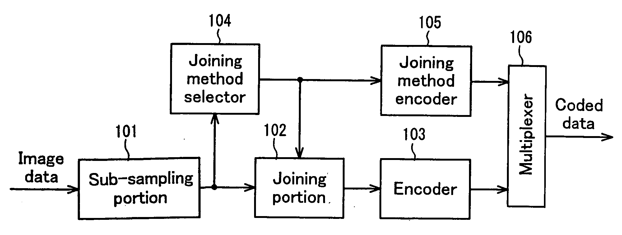
[0086]FIG. 1 is a block diagram showing an image coding apparatus of the first embodiment of the present invention. A sub-sampling portion 101 is a portion that sub-samples images of data; a joining portion 102 is a portion that joins the sub-sampled images of data; an encoder 103 is a portion that encodes the joined image data; a joining method selector 104 is a portion that selects an image data joining method from a plurality of joining methods; a joining method encoder 105 is a portion that encodes the information of the selected joining method; and a multiplexer 106 is a portion that multiplexes the encoded image data and the encoded information of the joining method to generate coded data.

[0087] Now, the image coding apparatus of the first embodiment will be described in detail with reference to the drawings.

[0088] Sub-sampling portion 101 sub-samples the input image data to half with respect to the horizontal direction, in the same manner as described in...

second embodiment

The Second Embodiment

[0127] Next, the second embodiment of the present invention will be described. In the first embodiment, the input images viewed from different viewpoints are input time-sequentially. In the second embodiment, the input images viewed from different viewpoints can be input in parallel.

[0128]FIG. 6 is a block diagram showing an image coding apparatus of the second embodiment. A first sub-sampling portion 601 and second sub-sampling portion 607 are portions that sub-sample image data; a joining portion 602 is a portion that joins the sub-sampled images of data; and a joining method selector 604 is a portion that selects the image data joining method from multiple joining methods. An encoder 603, a joining method encoder 605 and a multiplexer 606 provide the same functions as in the configuration of FIG. 1, so that description is omitted herein.

[0129] First sub-sampling portion 601 sub-samples the input right image and second sub-sampling portion 607 sub-samples th...

third embodiment

The Third Embodiment

[0133] Next, the third embodiment of the present invention will be described. This embodiment is characterized by linking the selecting process of the joining method with the coding process.

[0134]FIG. 7 is a diagram showing an example of coding a movie. Here, the figures represent the frame numbers of the frames. The symbol added to each coded frame represents the type of coding. Specifically, I indicates that the frame is coded by intra-frame coding, P indicates that the frame is coded by inter-frame coding.

[0135] In the example of FIG. 7, frame 0 is coded by intra-frame coding, frames 1 and 2 are omitted without being coded, frame 3 is coded by inter-frame coding. Similarly, frames 6 and 10 are coded by inter-frame coding, and frame 14 is coded next by intra-frame coding.

[0136] It is wasteful to effect a selection process of the joining method every frame in a coding scheme entailing frame-skipping. Therefore, in the third embodiment, in the image coding app...


PUM


Abstract

A sub-sampling portion (101) sub-samples images of data corresponding to the left and right viewpoints. A joining method selector (104) selects the joining method that minimizes the discontinuity at the boundary in the joined image when the sub-sampled images of data are joined. A joining portion (102) joins the plurality of images data, based on the selected joining method. An encoder (103) encodes the joined image data, and a joining method encoder (105) encodes the information of the joining method. A multiplexer (106) multiplexes these pieces of coded data. In this way, the continuity of the joined image is improved, whereby the coding efficiency is enhanced.

Description

TECHNICAL FIELD [0001] The present invention relates to an image coding apparatus, image decoding apparatus, recording medium and image recording apparatus for coding and decoding image data composed of multiple images observed from different viewpoints. BACKGROUND ART [0002] Conventionally, as a method of coding a stereo image by joining two still images taken from different viewpoints, a technology has been disclosed in Japanese Patent Application Laid-open Hei 11 No. 41627. [0003]FIG. 15 is a block diagram showing a coding apparatus for stereo images in this prior art technology. A sub-sampling portion 1501 is a portion that sub-samples still image data; a joining portion 1502 is a portion that joins the thinned out still image data; and an encoder 1503 is a portion that encodes the joined still image data. [0004] The operation of each portion will be described next. [0005] Sub-sampling portion 1501 sub-samples input still image data to half in the horizontal direction. Here, the...

Claims


Application Information

Patent Timeline
Patent Type & Authority Applications(United States)
IPC IPC(8): H04N19/587G06T9/00H03M7/30H04N5/7826H04N5/91H04N5/92H04N9/804H04N9/806H04N9/82H04N13/00H04N13/02H04N19/00H04N19/423H04N19/59H04N19/597H04N19/70
CPCH03M7/30H04N21/816H04N5/78263H04N9/8042H04N9/8047H04N9/8063H04N9/8205H04N9/8227H04N13/0003H04N13/0048H04N13/0066H04N13/007H04N19/00H04N19/597H04N19/70H04N19/46H04N19/61H04N19/60H04N19/85H04N19/59H04N21/21805H04N21/234345H04N21/236H04N21/431H04N21/4325H04N21/434H04N5/45H04N13/10H04N13/161H04N13/178H04N13/183H04N13/00H04N19/587
Inventor KATATA, HIROYUKIUCHIUMI, TADASHIYASUMOTO, TAKASHIHASEGAWA, SHINYANAGATAKI, SHINGOTSUJIMOTO, MASATOSHIITOH, MOTOHIRO
Owner SHARP KK
Why Eureka
Try Eureka