
Methods and devices for coupling electromagnetic radiation using diffractive optical elements

a technology of diffractive optical elements and electromagnetic radiation, applied in the direction of optics, bundled fibre light guides, instruments, etc., can solve the problems that the design of prior art optical star couplers is typically limited to providing coupling function for single-line, serial links

Inactive Publication Date: 2005-07-07
IBM CORP
View PDF57 Cites 9 Cited by
  • Summary
  • Abstract
  • Description
  • Claims
  • Application Information

AI Technical Summary

Problems solved by technology

In contrast, prior art optical star coupler designs are typically limited to providing coupling function for single-line, serial links.

Method used


Image

  • Methods and devices for coupling electromagnetic radiation using diffractive optical elements
  • Methods and devices for coupling electromagnetic radiation using diffractive optical elements
  • Methods and devices for coupling electromagnetic radiation using diffractive optical elements

Examples


Embodiment Construction

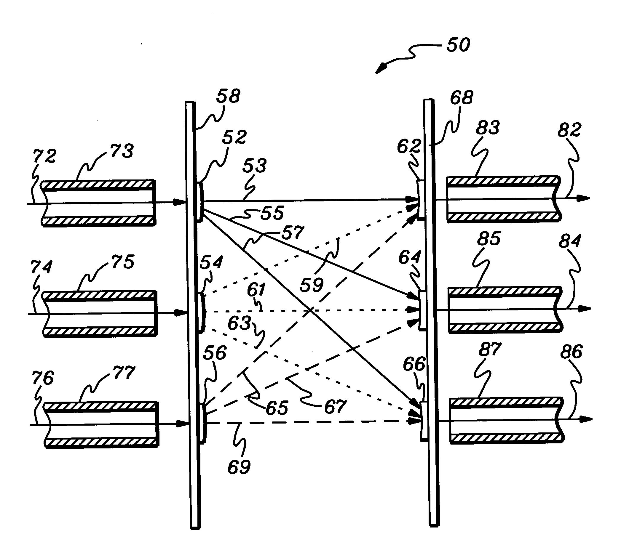
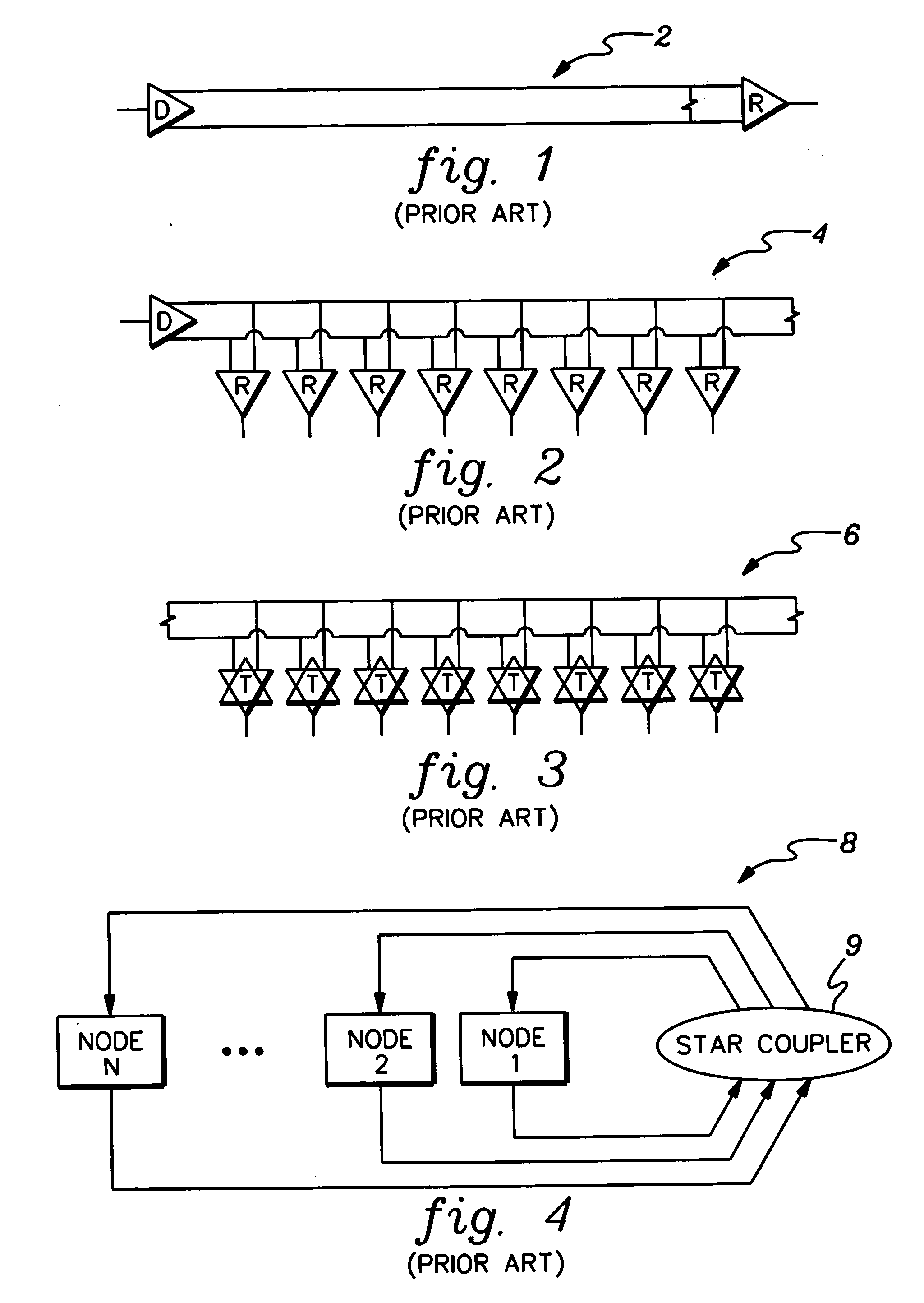
[0032]FIGS. 1, 2, 3, and 4 illustrate typical optical linkage systems according to the prior art. FIG. 1 is a schematic diagram of a point-to-point optical link system 2 between a single optical driver (D) and a single optical receiver (R). FIG. 2 is a schematic diagram of a multi-drop optical link system 4, according to the prior art having one driver (D) and multiple receivers (R). FIG. 3 is a schematic diagram of a multi-point optical link system 6 having multiple drivers and multiple receivers as indicated by transmitters (T) according to the prior art. FIG. 4 is a schematic diagram of a optical system 8 having an optical star coupler 9 linking multiple nodes in a computer network according to the prior art as proposed by J.-H. H a and T. M. Pinkston, in the Journal of Parallel Distributive Computing, vol. 60, 169-188, 2000. Aspects of the present invention make the system illustrated in FIG. 4 technically and economically feasible.

[0033] In the context of the present invention...


PUM


Abstract

Diffractive optical elements are used in methods and devices for coupling or distributing electromagnetic radiation. The diffractive optical. elements may be adapted to split one or more streams of radiation into multiple streams of radiation or to combine multiple streams of radiation to produce single streams. A plurality of diffractive optical elements may be fabricated on substrates by lithographic or molding methods. Diffractive optical elements that split one or more streams of radiation can be combined with diffractive optical elements that combine multiple streams of radiation to provide a coupling device, for example, a star coupler. The star coupler may be used in networked optical communication systems to provide multiple coupling between a plurality of optical drivers and a plurality of optical receivers. Aspects can be applied to any type of electromagnetic radiation having a wavelength that can be used as a medium for transferring information.

Description

TECHNICAL FIELD [0001] This invention relates in general to devices and methods for coupling electromagnetic radiation, that is, devices and methods for simultaneously transmitting optical signals from one set of sources to another set of receivers, for example, for use as optical star couplers and optical communications systems comprising diffractive optical elements. BACKGROUND OF THE INVENTION [0002] For the purpose of chip-to-chip, board-to-board, and system-to-system communications over high bandwidth distance links, the use of optical interconnection networks as replacements for their electrical counterparts is steadily growing. For links of high bit rate and distance (for example, greater than 10 meter-gigabits per second), optical transmission technology is increasingly providing better cost and performance versus electrical transmission technology. An additional advantage of optical transmission technology is that it can provide multi-point links without significant reducti...

Claims


Application Information

Patent Timeline
IPC IPC(8): G02B6/28G02B6/32G02B6/34
CPCG02B6/2848G02B6/34G02B6/32
Inventor BENNER, ALAN F.OGUNSOLA, OLUWAFEMI O.
Owner IBM CORP
Learn More