

Energy absorber and method for manufacturing the same
- Summary
- Abstract
- Description
- Claims
- Application Information
AI Technical Summary
Benefits of technology
Problems solved by technology
Method used
Image

Examples
first embodiment
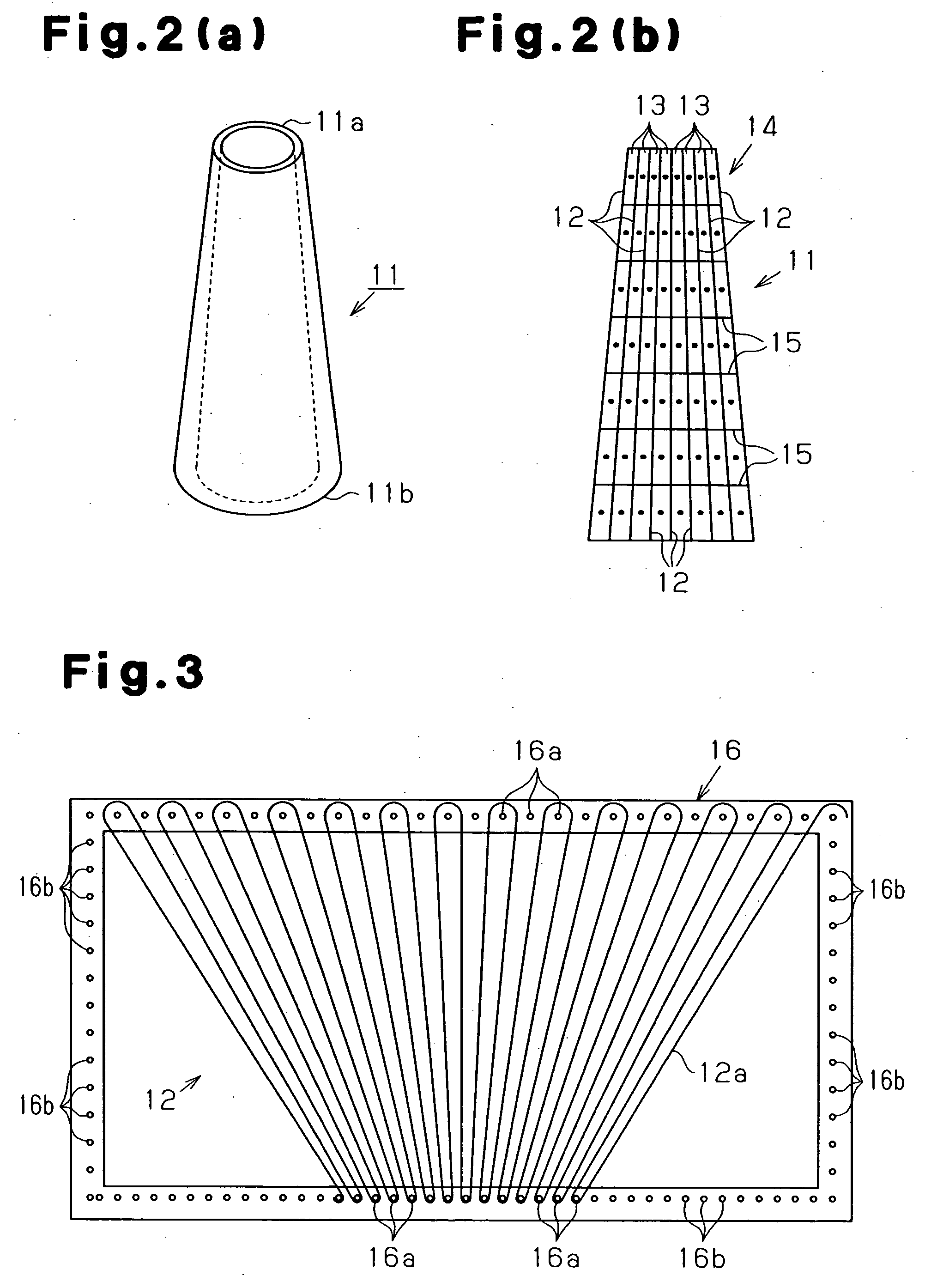
[0056] the present invention will now be described. As shown in FIG. 2(a), an energy absorber 11 is substantially cylindrical. As shown in FIG. 2(b), the energy absorber 11 is made of fiber-reinforced resin. The thickness of the energy absorber 11 varies from an upper end (distal end 11a) to a lower end (proximal end 11b). In other word, the thickness of the energy absorber 11 varies from a first end (distal end 11a) to a second end (proximal end 11b) of a compression direction of the energy absorber 11. The thickness of the energy absorber 11 is reduced from the proximal end 11b to the distal end 11a. The compression direction of the energy absorber 11 refers to a direction along which the energy absorber 11 receives compressive load when in use. In this embodiment, the energy absorber 11 receives compressive load from the distal end 11a along a vertical direction in FIG. 2(a). The base (proximal end 11b) of the energy absorber 11 is fixed to a predetermined position when in use. T...
third embodiment
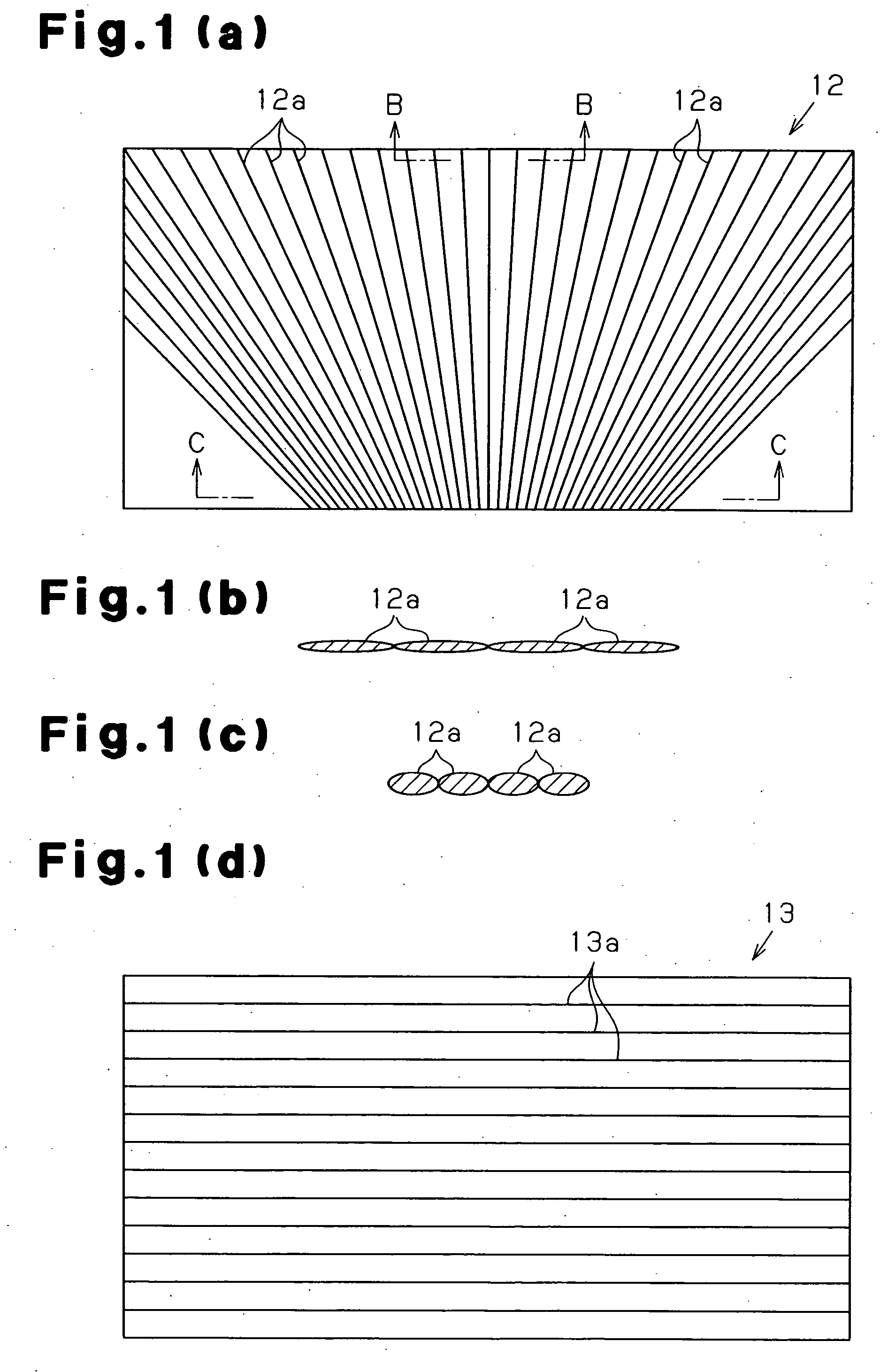
[0112] the present invention will now be described. As shown in FIG. 8(a), an energy absorber 111 is made of a fiber-reinforced resin having a fiber structure 112 as a reinforcing member. As shown in FIG. 8(b), the fiber structure 112 is formed as a plate and includes a stack of fiber layers 113 and binding threads 114. The stack of fiber layers 113 is arranged such that fiber bundles made of filament fibers have at least two axes, or a biaxial structure (in this embodiment, four axes, or a quadraxial structure). The binding threads 114 extend through the stack of fiber layers 113 along the thickness.
[0113] As shown in FIG. 8(a), the stack of fiber layers 113 includes an x thread layers 115 each formed of x threads 115a, a y thread layers 116 each formed of y threads 116a, and a bias thread layers 117, 118 each formed of bias threads 117a, 118a. The x threads 115a are arranged to extend along a direction in which compressive load is applied when the energy absorber 111 is used. The ...
fourth embodiment
[0151] the present invention will now be described. An energy absorber is made of fiber-reinforced resin. As shown in FIG. 18, a cross-section of the energy absorber 211 perpendicular to a compression direction when in use (direction indicated by arrow in FIG. 18) is varied along the compression direction. The magnitude of load needed for crushing changes depending on the position along the compression direction, accordingly.
[0152] The energy absorber 211 of this embodiment is formed such that the cross-sectional shape is continuously changed along the compression direction. The energy absorber 211 is in a state where a plate member is bent to have corners 212. The number of corners 212 at the proximal end 211b (right end as viewed in FIG. 18) is more than the number of corners 212 at the distal end 211a (left end as viewed in FIG. 18). The number of the corners 212 of the energy absorber 211 is four at the distal end 211a and eight at the proximal end 211b. That is, “the cross-sect...
PUM
 Abstract
Description
Claims
Application Information