Fixed constant velocity universal joint

a constant velocity, universal joint technology, applied in the direction of yielding couplings, couplings, rotary machine parts, etc., can solve the problems of deteriorating the constant velocity of the joint, slapping sound, hampering the original function, etc., to improve the nvh performance

Active Publication Date: 2005-07-07
NTN CORP
View PDF3 Cites 14 Cited by
  • Summary
  • Abstract
  • Description
  • Claims
  • Application Information

AI Technical Summary

Benefits of technology

[0007] It is a main object of the present invention to provide a fixed constant velocity universal joint in which a bending direction load occurring in changing the operating angle of the joint is reduced as means for improving the NVH performance.

Problems solved by technology

When the pocket clearance is set in the positive region, this clearance can cause the torque transmission balls and the cage to contact each other, possibly producing slapping sound.
Positive pocket clearances can also hamper the original function of the cage, or the function of retaining the torque transmission balls at appropriate positions, with a deterioration in the velocity constancy of the joint.
Nevertheless, the clearance might increase due to wear of the pocket surfaces, depending on the use conditions.

Method used


Image

  • Fixed constant velocity universal joint
  • Fixed constant velocity universal joint
  • Fixed constant velocity universal joint

Examples


Embodiment Construction

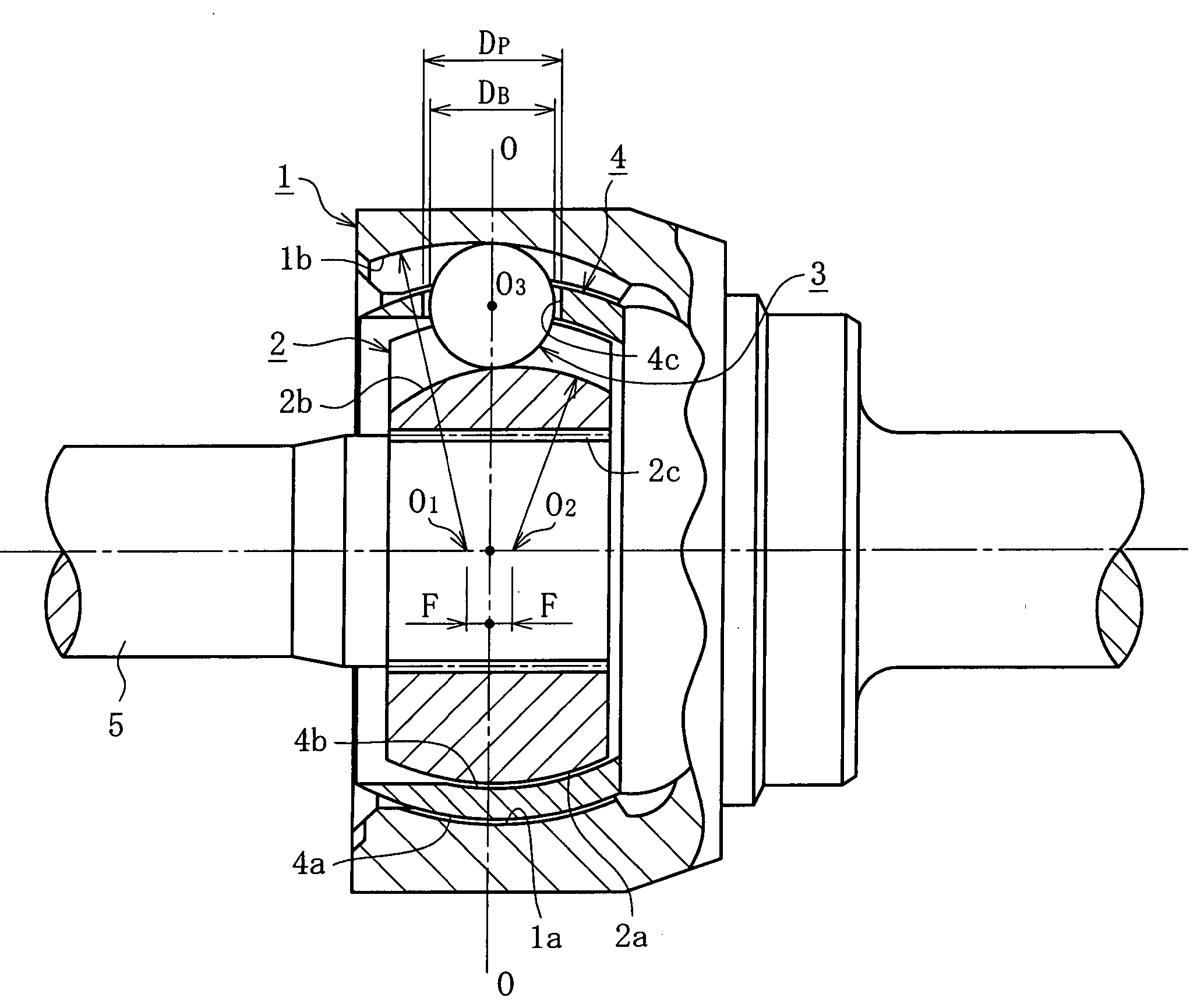
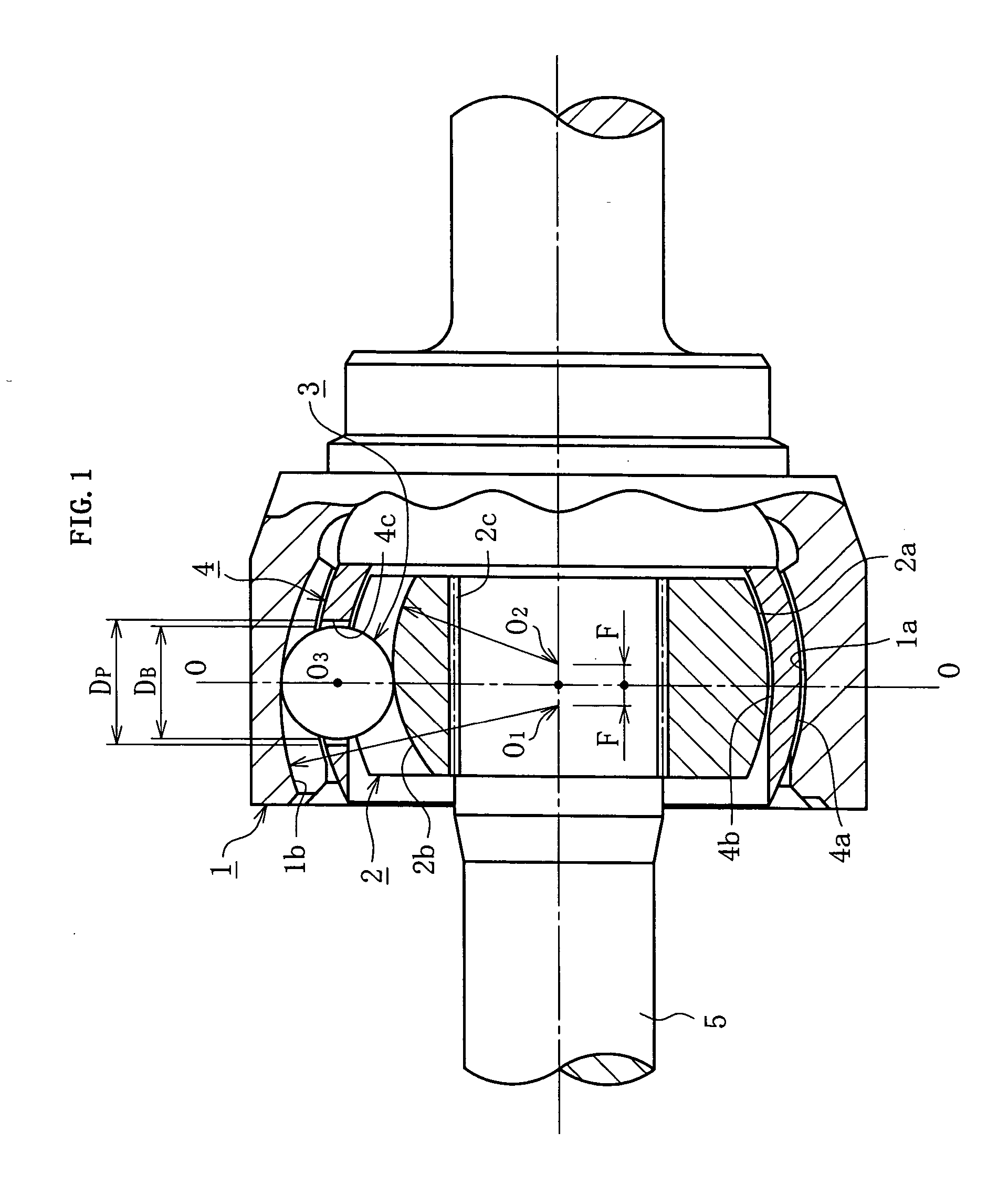
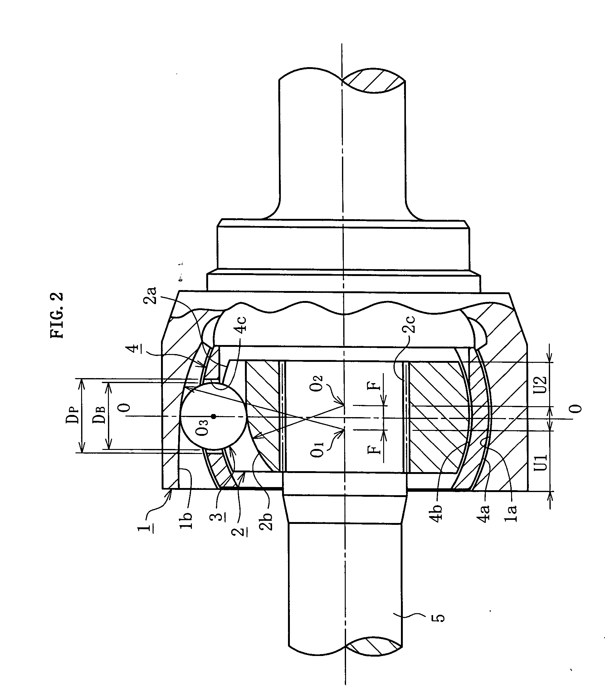
[0034] In the drawings, FIG. 1 shows a fixed constant velocity universal joint (BJ) which is a Rzeppa type constant velocity universal joint. FIG. 2 shows a fixed constant velocity universal joint of undercut-free type (UJ). The joint of FIG. 1 and the joint of FIG. 2 have the same cross sections, which are thus shown as a single cross-sectional view in FIG. 3. Note that the clearances are shown exaggerated in the diagrams.

[0035] Now, the constant velocity universal joint (BJ) shown in FIG. 1 consists chiefly of an outer ring 1, an inner ring 2, torque transmission balls 3, and a cage 4. The outer ring 1 is composed of a cup part and a shaft part. The shaft part establishes connection with one of two shafts to couple. The cup part has an inner spherical surface 1a of partially spherical shape. Eight track grooves 1b extending in the axial direction are formed in the inner spherical surface 1a at circumferential regular intervals. The inner ring 2 has an outer spherical surface 2a o...


PUM


Abstract

A fixed constant velocity universal joint includes: an outer ring having a plurality of track grooves extending axially in its inner spherical surface; an inner ring having a plurality of track grooves extending axially in its outer spherical surface; torque transmission balls arranged in ball tracks formed by cooperation of the track grooves of the outer ring and the track grooves of the inner ring; and a cage having pockets for retaining the torque transmission balls. The center of the track grooves of the outer ring and the center of the track grooves of the inner ring are offset from the spherical center of the inner spherical surface and the spherical center of the outer spherical surface, respectively, by the same distance axially in opposite directions. An axial clearance between the pockets and the torque transmission balls is set within the range of −0.006 and −0.035 mm. A spherical portion clearance between the cage and the inner ring is set so that a clearance-to-diameter ratio falls within the range of 0.9 and 2.3.

Description

BACKGROUND OF THE INVENTION [0001] 1. Field of the Invention [0002] The present invention relates to a fixed constant velocity universal joint. Constant velocity universal joints are components of power transmission systems in motor vehicles and various industrial machines, intended to couple a rotational shaft on the driving side and a rotational shaft on the driven side for the sake of torque transmission at constant angular velocity. The constant velocity universal joints are divided into fixed type and slide type. The slide type allows both an angular displacement and an axial displacement while the fixed type allows an angular displacement alone. [0003] 2. Description of the Related Art [0004] When a fixed constant velocity universal joint forms an angle, there occurs a force in the bending direction. Take, for example, a fixed constant velocity universal joint on the drive shaft of a front-wheel drive car. In steering the car, an outer ring fixed to the front axle forms an ang...

Claims


Application Information

Patent Timeline
Patent Type & Authority Applications(United States)
IPC IPC(8): F16D3/2245
CPCF16D3/2237Y10S464/906F16D2003/22309F16D3/2245
Inventor NAKAGAWA, TOHRUWADA, MORIHIRO
Owner NTN CORP
Why Eureka
Try Eureka