External bone/joint fixation device

a fixation device and bone/joint technology, applied in the field of external orthopedic bone/joint fixation devices, can solve the problems of inability to achieve the desired compression, instability, and difficulty in achieving accurate in-plane compression with current fixation devices, and achieve the effect of less expensive and accurate application of in-plane compression

Active Publication Date: 2005-07-07
BIOMET CV
View PDF22 Cites 58 Cited by
  • Summary
  • Abstract
  • Description
  • Claims
  • Application Information

AI Technical Summary

Benefits of technology

[0017] In a specific form, the present invention is an external foot / ankle fixation device. The fixation device has a preferably, but not necessarily, one-piece frame component and a positionable cross bar that allows the attachment of generally anterior / posterior directed fixation wires (e.g. olive wires) or rods emanating from the foot / ankle of a patient. The fixation wires may be attached in various angles relative to an anterior / posterior plane. The external fixation device provides a stable fixation platform both in-plane and out-of-plane of the object of fixation (e.g. foot or ankle).
[0018] Through the cross bar, the fixation device also provides various degrees of angulation of anterior / posterior directed fixation wires in two planes. Posterior angulation components may be provided to the posterior portion of the frame component that provides additional fixation wire / rod angulation variations. An optional elevator component may be attached to the bottom of the frame component that does not obstruct access to the soft tissues on the bottom of the foot while still protecting the bottom of the foot from contaminated surfaces.
[0019] The ring frame is constructed as a closed, one-piece platform. This provides a stable platform for object fixation. This approach is simple and less expensive than modular alternatives. The present invention solves the instability problems of current open U-ring foot / ankle fixation devices. Additionally, the bottom of the foot of the patient may also be protected. Moreover, the present invention allows the accurate application of in-plane compression using tension or fixation wires. The present invention also allows the capture of fixation wires tied to various degrees of angulation in a posterior / anterior direction.

Problems solved by technology

These systems, however, suffer problems with respect to being able to achieve the desired compression results, e.g. the ability to adequately externally fix the wires and provide controlled compression.
This can lead to instability problems.
Moreover, it is difficult to achieve accurate in-plane compression with current fixation devices.
Tensioning bent wires, however, does not provide a controlled or measurable amount of compression on the desired area of the ankle / foot.
This technique is time consuming and costly.

Method used


Image

  • External bone/joint fixation device
  • External bone/joint fixation device
  • External bone/joint fixation device

Examples


Embodiment Construction

[0043] While the invention is susceptible to various modifications and alternative forms, specific embodiments thereof have been shown by way of example in the drawings and will herein be described in detail. It should be understood, however, that there is no intent to limit the invention to the particular forms disclosed, but on the contrary, the intention is to cover all modifications, equivalents and alternatives falling within the spirit and scope of the invention as defined by the appended claims.

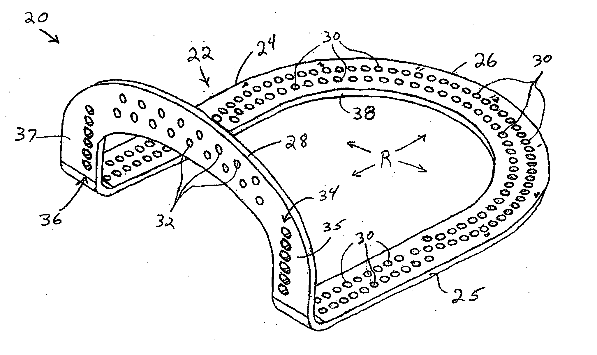
[0044] Referring now to FIG. 1, there is depicted an exemplary embodiment of a frame component (frame), generally designated 20, of a bone / joint fixation device configured in accordance with the principles of the subject invention. While the present bone / joint fixation device or component is shown and described with respect to a foot / ankle device or component, it should be appreciated that the principles and / or the particular embodiments of the present foot / ankle fixation device / compo...


PUM


Abstract

An external foot/ankle fixation device has a one-piece frame component and a positionable cross bar that allows the attachment of generally anterior/posterior directed fixation wires or rods emanating from the foot/ankle of a patient. The external fixation device provides a stable fixation platform both in-plane and out-of-plane of the object of fixation (e.g. foot or ankle). The fixation device through the cross bar also provides various degrees of angulation of anterior/posterior directed wires in two planes. Posterior angulation components may be provided to the posterior portion of the frame component that provide additional fixation wire/rod angulation variations. Compression rails may also be provided. An optional elevator component may be attached to the bottom of the frame component that does not obstruct access to the soft tissues on the bottom of the foot. The elevator component protects the bottom of the foot from contaminated surfaces.

Description

FIELD OF THE INVENTION [0001] The present invention relates to external orthopedic fixation devices and, more particularly, pertains to an external orthopedic bone and / or joint fixation component, such as for the foot and / or ankle. BACKGROUND OF THE INVENTION [0002] In the orthopedic reconstruction of a patient's bone and / or joint, particularly with respect to bone repair thereof, it is necessary to keep the repaired bone and / or joint in an immobilized and stable state during the healing process. This is accomplished by using a frame construct that typically includes many different fixation components. The various fixation components are utilized to build a fixation device for immobilizing the bone and / or joint. One such fixation component may be an immobilization platform or platform construct. [0003] In the area of the foot and / or ankle, what is known as a foot frame is generally utilized. Current foot frames are typically of an open U-ring type. The open U-rings may comprise a si...

Claims


Application Information

Patent Timeline
Patent Type & Authority Applications(United States)
IPC IPC(8): A61B17/56A61B17/64
CPCA61B17/6425
Inventor COOPER, PAULELSAKKA, MAMDOUHMOHRMAN, JOELPEPPER, JOHN
Owner BIOMET CV
Why Eureka
Try Eureka