Method for operating a floor cleaning system, and floor cleaning system for use of the method

Inactive Publication Date: 2005-07-14
ALFRED KARCHER GMBH & CO KG
View PDF4 Cites 217 Cited by
  • Summary
  • Abstract
  • Description
  • Claims
  • Application Information

AI Technical Summary

Benefits of technology

[0008] In a method of the generic type, this object is achieved, according to the invention, by the suction unit being selectively operated with a maximum suction power or a reduced suction power. According to the invention, it is possible to reduce the noise produced by the floor cleaning appliance by the suction unit being operated with a reduced suction power. A reduced-power operating mode of this type is advantageous in particular when the f

Problems solved by technology

If the floor cleaning system is used at times at which the production of noise is considered particula

Method used


Image

  • Method for operating a floor cleaning system, and floor cleaning system for use of the method
  • Method for operating a floor cleaning system, and floor cleaning system for use of the method
  • Method for operating a floor cleaning system, and floor cleaning system for use of the method

Examples


Embodiment Construction

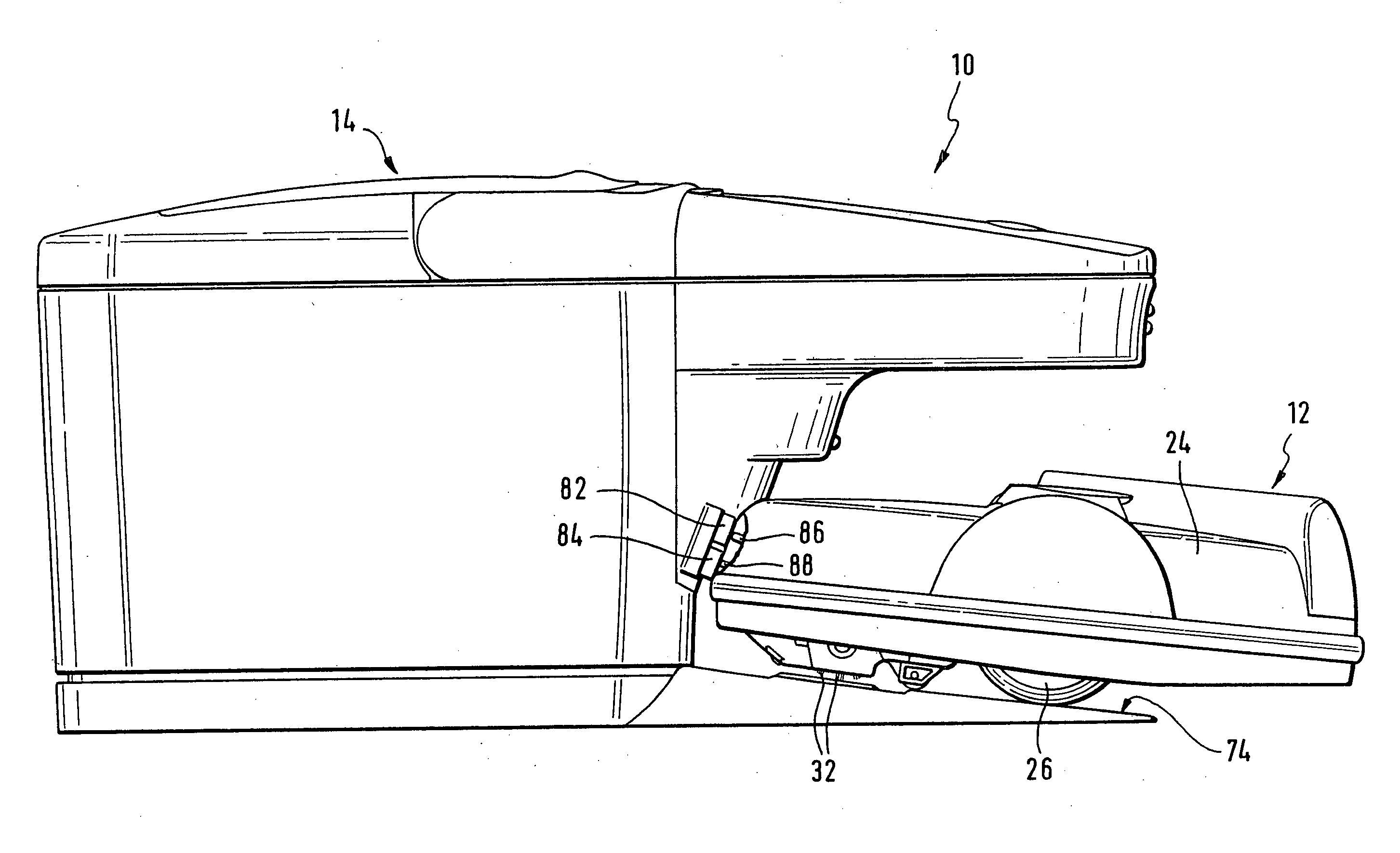
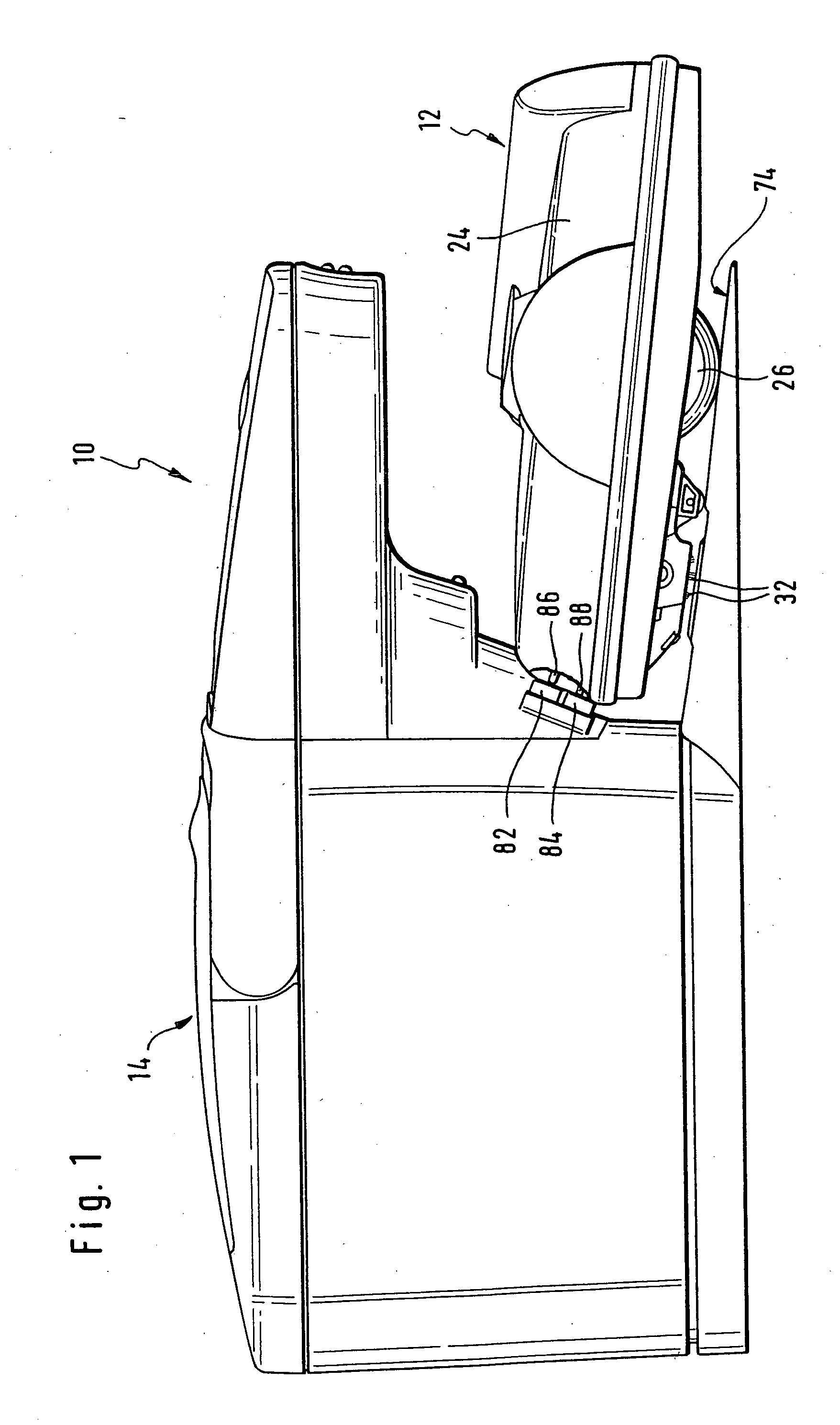
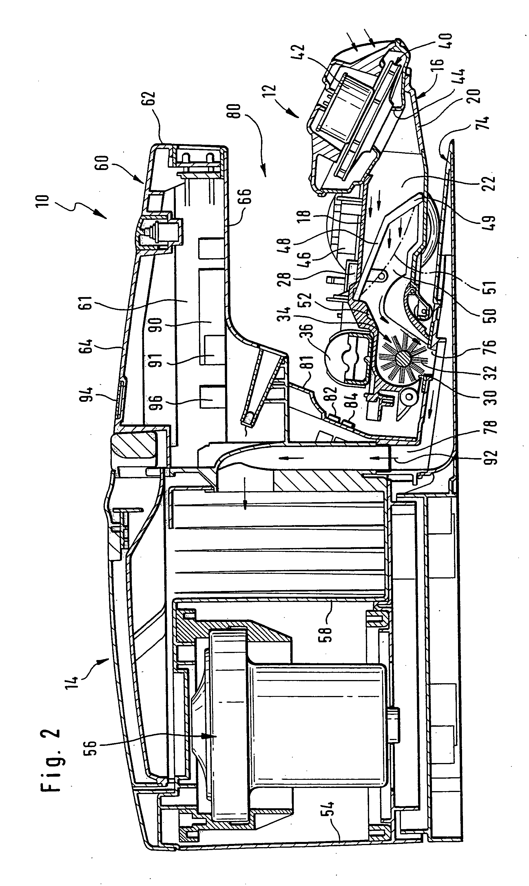
[0028]FIGS. 1 and 2 diagrammatically depict a floor cleaning system according to the invention, which is denoted overall by reference numeral 10 and comprises a self-propelled and self-steering suction appliance 12 and a central suction station 14.

[0029] The mobile suction appliance 12 comprises a housing 16 with a top wall 18 and a bottom wall 20, which between them define a suction passage 22. A cover 24, which is not shown in FIG. 2 for the sake of clarity, is fitted onto the top wall 18. The housing 16 forms a chassis of the mobile suction appliance 12. Two drive wheels 26, each with an associated electric drive motor, which is known per se and not illustrated, are mounted rotatably on the housing 16 in a manner which is known per se and is therefore not illustrated in more detail in the drawing. The drive motors are controlled by means of an electronic control unit 28, which is known per se and is therefore only diagrammatically illustrated in FIG. 2 and which is connected to ...


PUM


Abstract

The invention relates to a method for operating a floor cleaning system having a central suction station with which there is associated a self-propelled and self-steering suction appliance, dirt being picked up from a floor surface that is to be cleaned by means of the suction appliance and being transferred into a dirt collection vessel of the suction appliance, and the suction station having a suction unit, and the dirt collection vessel being sucked out by means of the suction unit. To refine the method in such a manner that the levels of noise produced by the floor cleaning system can be reduced, it is proposed, according to the invention, that the suction unit is optionally operated with a maximum suction power or a reduced suction power. The invention also proposes a floor cleaning system for carrying out the method.

Description

[0001] This application is a continuation of international application number PCT / EP 03 / 06222 filed on Jun. 13, 2003.[0002] The present disclosure relates to the subject matter disclosed in international application number PCT / EP 03 / 06222 of Jun. 13, 2003 and German application number 102 31 384.9 of Jul. 8, 2002, which are incorporated herein by reference in their entirety and for all purposes. BACKGROUND OF THE INVENTION [0003] The invention relates to a method for operating a floor cleaning system having a central suction station with which there is associated a self-propelled and self-steering suction appliance, dirt being picked up from a floor surface that is to be cleaned by means of the suction appliance and being transferred into a dirt collection vessel of the suction appliance, and the suction station having a suction unit, and the dirt collection vessel being sucked out by means of the suction unit. [0004] Moreover, the invention relates to a floor cleaning system for us...

Claims


Application Information

Patent Timeline
IPC IPC(8): A47L5/00A47L5/38A47L7/00A47L9/00A47L9/10A47L9/28B08B7/00E01H1/08
CPCA47L5/38A47L7/0047A47L9/0081A47L9/106A47L9/2805A47L2201/024A47L9/2852A47L9/2857A47L9/2873A47L9/2884A47L9/2842
Inventor KEPPLER, JOACHIMSKOUMAL, ROGERBENZLER, GOTTFRIED
Owner ALFRED KARCHER GMBH & CO KG
Why Eureka
Try Eureka