Radiological imaging apparatus and its detector unit

a detector unit and imaging apparatus technology, applied in the direction of instruments, x/gamma/cosmic radiation measurement, radiation control devices, etc., can solve the problems of insufficient structure studies and difficulty in maintaining, and achieve the effect of reducing noise components, suppressing noise superimposition, and facilitating space shielding

Inactive Publication Date: 2005-07-14
HITACHI LTD
View PDF14 Cites 10 Cited by
  • Summary
  • Abstract
  • Description
  • Claims
  • Application Information

AI Technical Summary

Benefits of technology

The patent describes a device that prevents electromagnetic waves and light from interfering with the detection of radiation. It achieves this by using a cylinder filled with a material that blocks these interference sources. The device also includes a cover that further protects the detectors. This design allows for easier replacement of the detectors and improves the arrangement density of the detectors, resulting in a clearer image.

Problems solved by technology

This patent describes a problem faced by conventional radiological imaging devices like PET machines - they require too many detectors placed closely together to achieve high-resolution images but maintaining them can be challenging. The objective of this invention is to create a device that allows easy replacement of detectors while also increasing their arrangement density.

Method used


Image

  • Radiological imaging apparatus and its detector unit
  • Radiological imaging apparatus and its detector unit
  • Radiological imaging apparatus and its detector unit

Examples


first embodiment

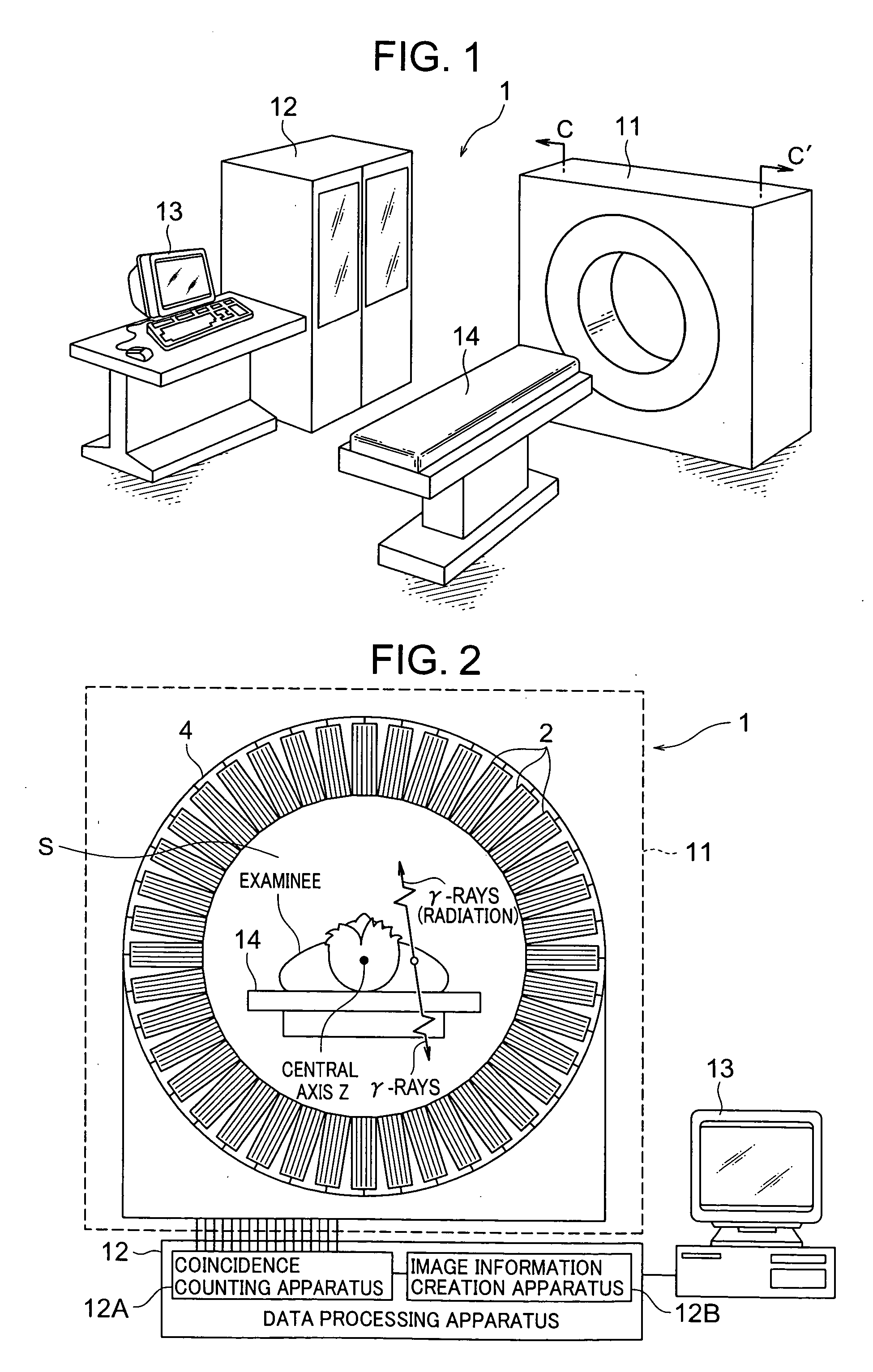
[0038] With reference to FIGS. 1 to 7, a first embodiment of the present invention will be explained.

[0039] As shown in FIG. 1, a PET apparatus 1 (radiological imaging apparatus) is constructed by including an imaging apparatus 11, a data processing apparatus 12 which processes detection data obtained by this imaging apparatus 11 and converts the detection data to image data, a display device 13 which displays the image data (PET image information) output from this data processing apparatus 12 two-dimensionally or three-dimensionally and an examining table 14 on which an examinee is laid.

[0040] The examinee is given radiopharmaceutical, for example, fluorodeoxyglucose (FDG) containing 18F having a half life of 110 minutes and pairs of γ-rays (radiation) generated when FDG positrons are annihilated are emitted from within the body of the examinee in directions of 180°±0.6° simultaneously. The radiopharmaceutical used in an inspection using the PET apparatus 1 emits positrons each o...

second embodiment

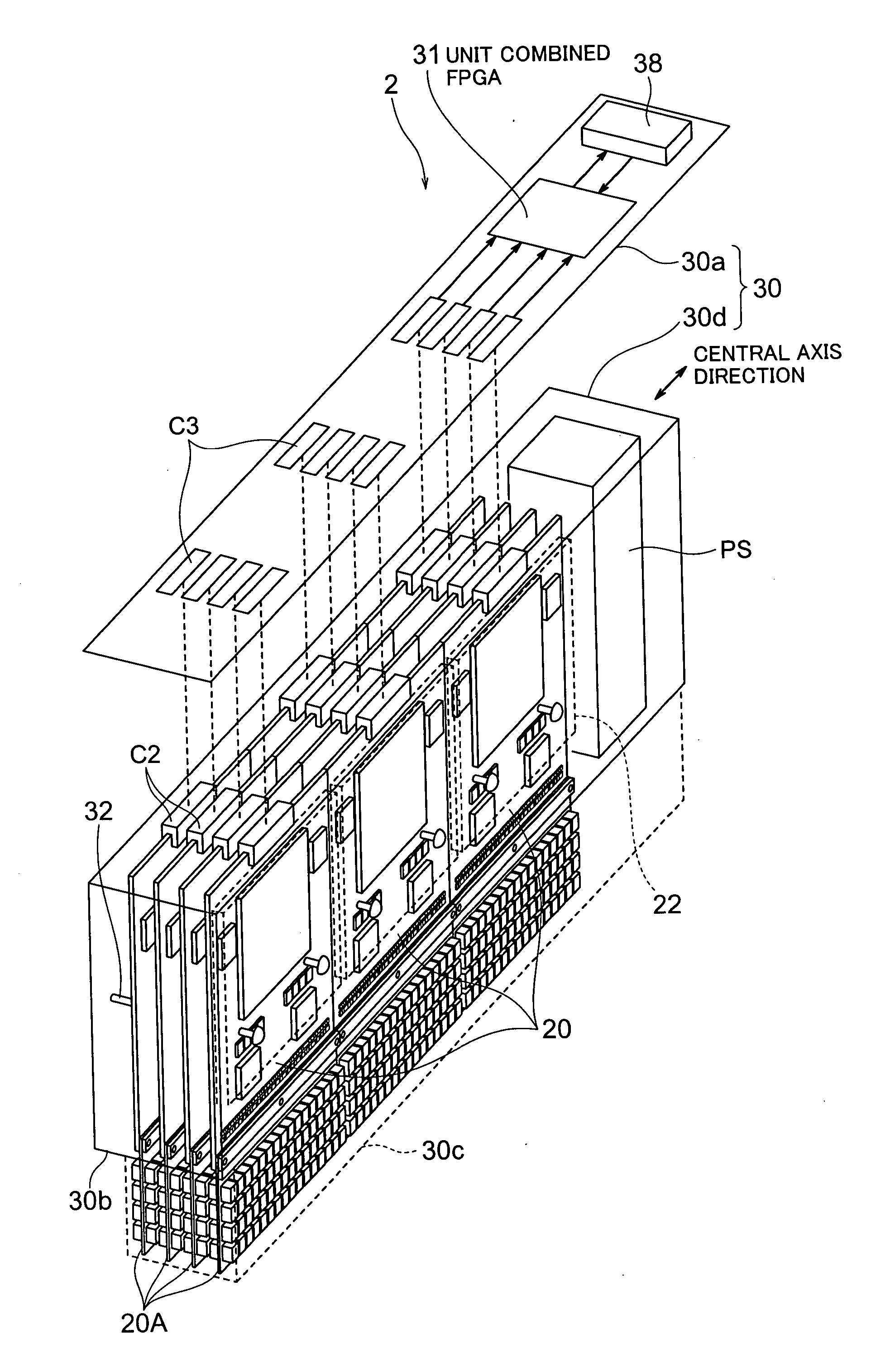
[0087] With reference to FIGS. 8A, 8B and 9, a PET apparatus which is a radiological imaging apparatus according to a second embodiment of the present invention will be explained. The same components in this embodiment as those in the first embodiment are assigned the same reference numerals and the corresponding components are suffixed with “′” and detailed explanations thereof will be omitted. The PET apparatus in this embodiment differs from the aforementioned PET apparatus 1 in the structure of the detector unit. The rest of the structure of the PET apparatus of this embodiment is the same as that of the PET apparatus 1. An imaging apparatus 11′ used for the PET apparatus in this embodiment has a structure with the detector unit 2 of the imaging apparatus 11 replaced by a detector unit 2′. The detector unit 2′ used for the PET apparatus in this embodiment consists of a plurality of combined substrates 20′ arranged in parallel in a housing 30 in parallel to the narrow side walls ...


PUM


Abstract

A radiological imaging apparatus capable of improving an arrangement density of semiconductor radiation detectors and detector units thereof, each detector unit consisting of a plurality of combined substrates having a detector substrate which includes semiconductor radiation detectors and a signal processing substrate which includes integrated circuits, housed in a housing. The detector substrate protrudes outward from an opening of the housing. A plurality of detector units are attached to a ring-shaped unit support section in a circumferential direction thereof. More specifically, the detector substrate protrudes inward from the unit support section and the housing is attached to the unit support section.

Description


Claims


Application Information

Patent Timeline
Owner HITACHI LTD
Why Eureka
Try Eureka