Probe card

a technology of rectilinear probes and probes, applied in the field of probe cards, can solve the problems of easy breakage of rectilinear probes, difficult to dispose of probes at narrow pitch, and bringing in contact with probes, etc., and achieves the effect of high complexity

Inactive Publication Date: 2005-07-14
NIHON DENSHIZAIRYO
View PDF6 Cites 21 Cited by
  • Summary
  • Abstract
  • Description
  • Claims
  • Application Information

AI Technical Summary

Benefits of technology

[0009] The present invention has been originally conceived and it is an object of the invention to provide a probe card capable of a stable contact thereof with electrodes on a measurement objective and of arranging probes at a narrow pitch so as to be adapted for high complexity in an integrated circuit as the measurement objective.

Problems solved by technology

The probes have been disposed at a narrower pitch in progress toward higher complexity in an integrated circuit, leading to a possibility that a curved portion of a probe is brought into contact with the next probe.
Hence, it has been hard to dispose the probes at the narrow pitch.
Therefore, a rectilinear probe is easy to be broken and has difficulty obtaining a contact pressure necessary for measurement.
Moreover, since a rectilinear probe is also hard to scrape an oxide film on an electrode as a measurement objective by sliding the probe sideways on a surface of the electrode, the probe again has difficulty ensuring as table contact with the electrode as a measurement objective.
If probes are disposed at a narrow pitch, great congestion arises of electrodes and wiring patterns on a base plate connected electrically to the probes, making placement thereof difficult.
In this regard as well, it is difficult to dispose the probes at a narrow pitch.

Method used


Image

  • Probe card
  • Probe card
  • Probe card

Examples


embodiment 1

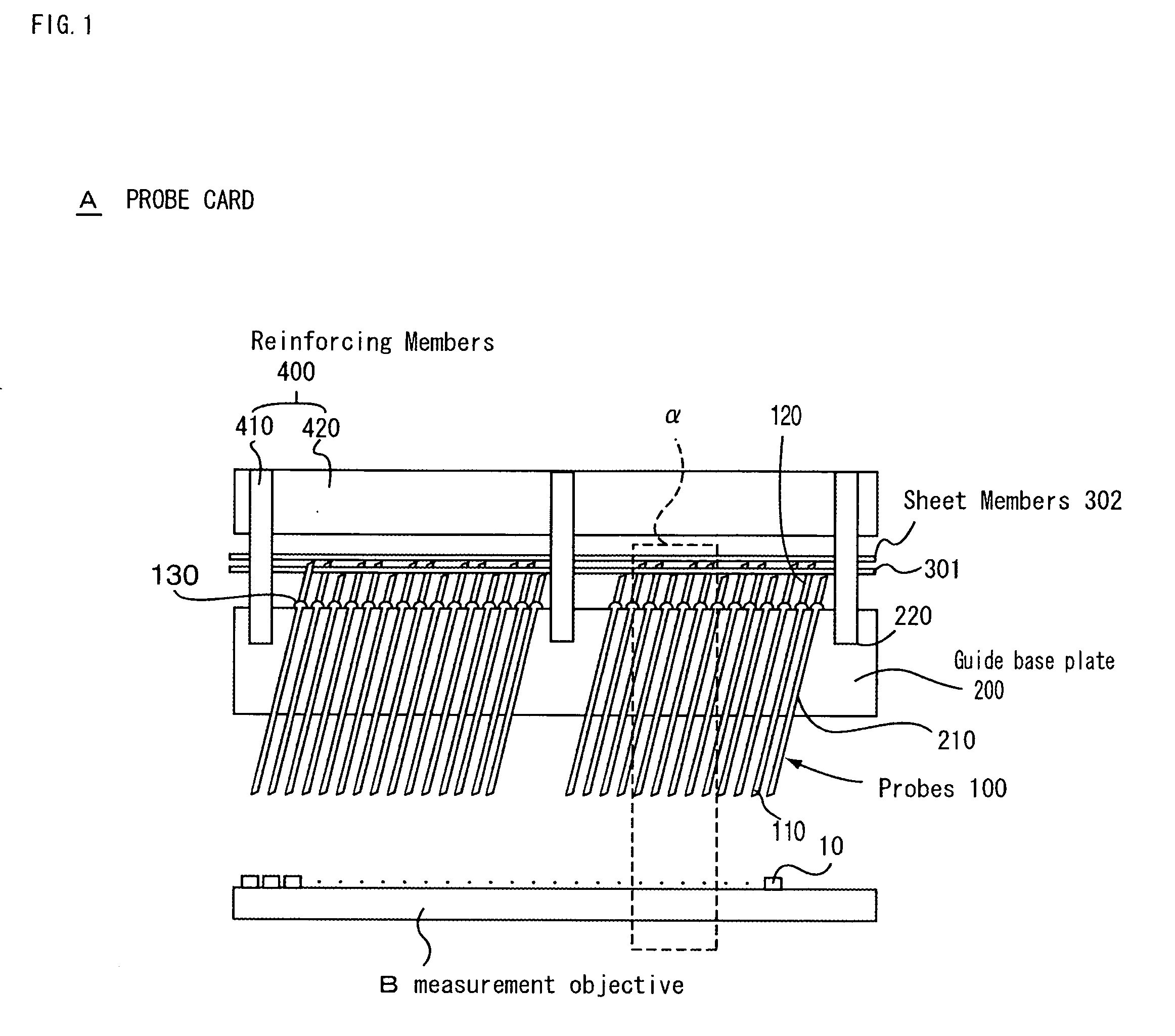
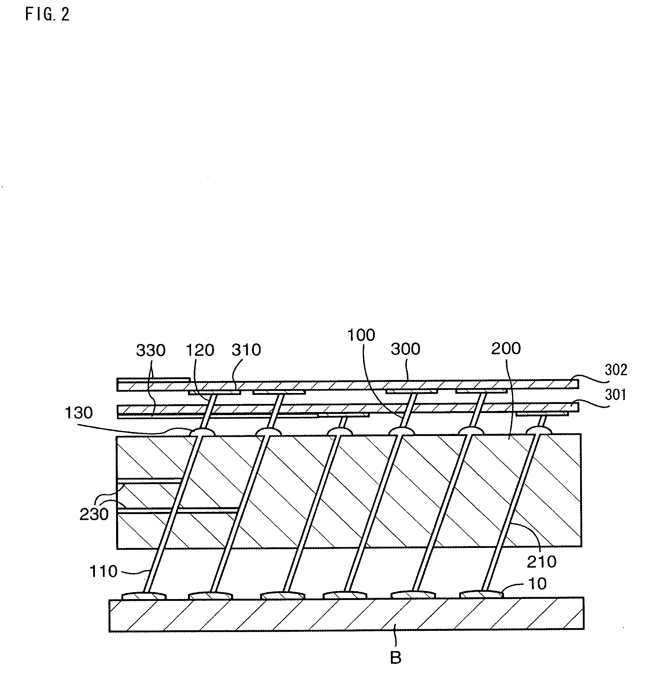
[0029] First of all, description will be given of a probe card related a first embodiment of the present invention with reference to the accompanying drawings. FIG. 1 is a schematic sectional view of a probe card related to the first embodiment of the present invention, FIG. 2 is an enlarged view of an α portion of the probe card, FIGS. 3(a) and 3(b) are views showing a guide base plate of the probe card, wherein FIG. 3(a) is a schematic plan view and FIG. 3(b) is a schematic sectional view, FIGS. 4(a) and 4(b) are views showing a reinforcing member for the probe card, wherein FIG. 4(a) is a schematic plan view, and FIG. 4(b) is a schematic sectional view, FIGS. 5(a) and 5(b) are views showing a sheet member of the probe card, wherein FIG. 5(a) is a schematic plan view and FIG. 5(b) is a schematic sectional view.

[0030] The probe card A shown in FIGS. 1 and 2 includes a plural rectilinear probes 100; a guide base plate 200 in which provided are plural guide holes 210 into which the ...

embodiment 2

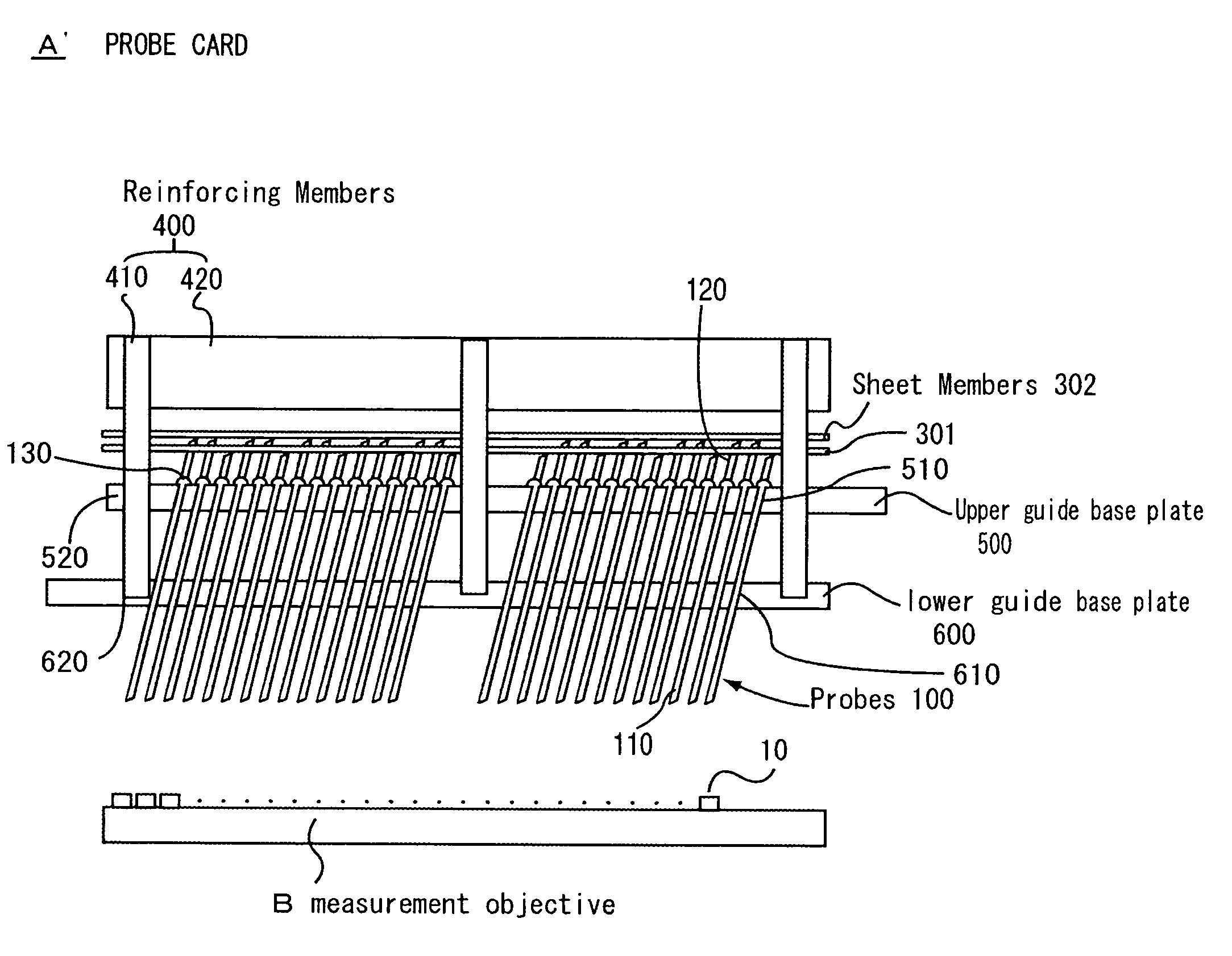
[0044] Description will be given of a probe card related to the second embodiment of the present invention with reference to the accompanying drawings. FIG. 6 is a schematic sectional view of a probe card related to the second embodiment of the present invention and FIG. 7 is a schematic sectional view showing an attaching process for probes of the probe card.

[0045] The probe card A′ shown in FIG. 6 is of almost the same construction as the probe card A. The probe A′ is different from the probe card A in that an upper guide base plate 500 and a lower guide plate 600 are employed instead of the guide base plate 200. Therefore, detailed description will be given of different portions of the construction, but none of description of duplicated portions is given. Note that the same symbols as in the first embodiment are used to indicate the same members.

[0046] A silicon base plate similar to the guide base plate 200 is employed as the upper guide base plate 500. The upper guide base pl...


PUM


Abstract

A probe card including rectilinear probes; a guide base plate having an insulating property, in which a plurality of guide holes are formed through which the probes are inserted in a freely movable manner and a length of a guide hole is shorter than a length of a probe; and a plurality of sheet members having an insulating property, disposed above the guide base plate facing the plate, and laminated one on another with a spacing therebetween so as not to be in contact with one another. The tail ends of some of the probes can be brought into contact with the electrode pads on a lowest sheet member, and the tail ends of the other probes penetrate through the lowest sheet member so as to be enabled to be in contact with electrode pads on other sheet members.

Description

BACKGROUND OF THE INVENTION [0001] 1. Field of the Invention [0002] The present invention relates to a probe card used in measuring electric characteristics of a measurement objective. [0003] 2. Prior Art [0004] As a probe card of this kind, there has been available one including a base plate and probes each having a curved portion and attached to the base plate (see Patent literature 1). The probe card is used in a way such that the distal end of a probe is overdriven on an electrode as a measurement objective in contact therewith to bend the curved portion of the probe, whereby not only is a predetermined contact pressure, necessary for measurement, against the electrode as a measurement objective obtained, but also the distal end is slid on a surface of the electrode as a measurement objective to scrape an oxide film attached on the surface for ensuring stable contact with the electrode as a measuring objective. [0005] Patent literature 1: JP-A No. 2003-215163. [0006] The probes ...

Claims


Application Information

Patent Timeline
Patent Type & Authority Applications(United States)
IPC IPC(8): H01L21/66G01R1/073
CPCG01R1/07371H01L22/00
Inventor MACHIDA, KAZUMICHIURATA, ATSUOKIMURA, TEPPEI
Owner NIHON DENSHIZAIRYO
Why Eureka
Try Eureka