Liquid crystal display

a liquid crystal display and display technology, applied in non-linear optics, instruments, optics, etc., can solve problems such as narrow viewing angles, and achieve the effect of wide viewing angles

Inactive Publication Date: 2005-07-14
SAMSUNG DISPLAY CO LTD
View PDF30 Cites 18 Cited by
  • Summary
  • Abstract
  • Description
  • Claims
  • Application Information

AI Technical Summary

Benefits of technology

[0017] In the EOC-LCD according to the embodiments of the present invention, the liquid crystal molecules are symmetrically aligned to the surface which is equal distance from each of the electrodes. Accordingly, the phase retardation of the transmitted light is symmetrically compensated, thereby obtaining a wide viewing angle.

Problems solved by technology

This type of TN-LCD unfortunately results in having a narrow viewing angle.

Method used


Image

  • Liquid crystal display
  • Liquid crystal display
  • Liquid crystal display

Examples


Embodiment Construction

[0029] Embodiments of the present invention will become apparent from a study of the following detailed description when viewed in light of drawings.

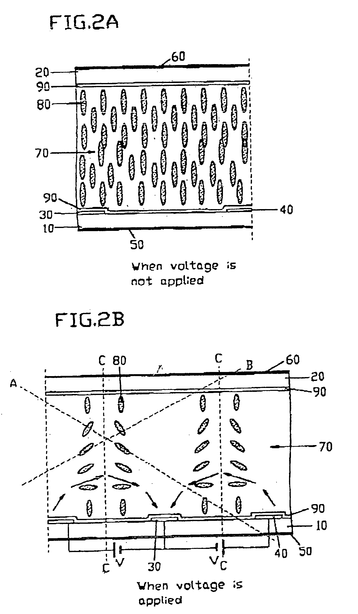
[0030]FIGS. 2A to 2C and 3A to 3C illustrate basic driving principles of EOC-LCDs according to a first and a second embodiment of the present invention.

[0031] Referring to FIGS. 2 to 2C and 3A to 3C, a pair of transparent glass substrates 10 and 20 respectively having alignment films 90 are facing each other. Two linear electrodes 30 and 40 parallel to each other are formed on the inner surface of the lower substrate 10 of the substrates 10 and 20. The liquid crystal layer 70 is injected between the substrates 10 and 20. The liquid crystal molecules 80 of the liquid crystal layer 70 are homeotropically aligned, and thus they are perpendicular to the substrates 10 and 20. The liquid crystal molecules 80 may have a pre-tilt angle with respect to the substrates 10 and 20. The electrodes 30 and 40 may be transparent or opaque conductive m...


PUM

PropertyMeasurementUnit
angleaaaaaaaaaa
bent angleaaaaaaaaaa

Abstract

Two electrodes parallel to each other are formed on one of two substrates, homeotropic alignment films are formed on the substrates and a liquid crystal material having positive dielectric anisotropy is injected between the substrates. When a voltage is appled to the two electrodes, a parabolic electric field between the electrodes drives the liquid crystal molecules. Since the generated electric field is symmetrical with respect to the boundary-plane equal distance from each of the two electrodes, the liquid crystal molecules are symmetrically aligned with respect to the boundary-plane, and the optical characteristic is compensated in both regions divided by the boundary-plane, thereby obtaining a wide viewing angle. The electric field does not exert influences on the liquid crystal molecules on the boundary-plane since the electric field on the boundary-plane is parallel to the substrates and perpendicular to the two electrodes and thus, it is perpendicular to the liquid crystal molecules. Here, the polarization of the light is changed while passing through the liquid crystal layer and as a result, only a part of the light passes through the polarizing plate The transmittance of the light can be varied by controlling the magnitude of voltage applied to the two electrodes. The alignment direction of the liquid crystal molecules is changed in both regions of a bent portion of the electrodes by forming the electrodes in the saw shape in a pixel or in by pixel, and the retardation of the light is compensated, thereby obtaining a wider viewing angle.

Description

BACKGROUND OF THE INVENTION [0001] (a) Field of the Invention [0002] The present invention relates to a liquid crystal display having a wide viewing angle. [0003] (b) Description of the Related Art [0004] Generally, a conventional liquid crystal display (LCD) includes two substrates having electrodes and liquid crystal injected therebetween. The voltage difference between the electrodes yields an electric field, and the molecules of the liquid crystal are re-arranged by the electric field. The polarization of incident light is varies due to the re-arrangement of the liquid crystal molecules. [0005] Hereinafter, the conventional LCD is explained in detail with reference to the accompanying drawings. [0006]FIGS. 1A and 1B are sectional views of a conventional twisted-nematic liquid crystal display (TN-LCD). The TN-LCD in FIG. 1A includes transparent glass substrates 1 and 2 facing each other, a liquid crystal layer 7 inserted between the substrates 1 and 2, and electrodes 3 and 4 form...

Claims


Application Information

Patent Timeline
Patent Type & Authority Applications(United States)
IPC IPC(8): G02F1/1337G02F1/1343
CPCG02F2001/133742G02F1/134363G02F1/133742
Inventor KIM, KYEONG-HYEONSHIM, JUNG-UKPARK, SEUNG-BEOMSONG, JANG-KUN
Owner SAMSUNG DISPLAY CO LTD
Why Eureka
Try Eureka