Coin hopper

a coin hopper and coin technology, applied in the field of coin hoppers, can solve the problems of inaccurate dispensing of predetermined coins, poor dispensing efficiency, and generation of idle states, and achieve the effects of preventing joggling of coins in the chute, preventing erroneous coin sensor operation, and accurately counting coins

Active Publication Date: 2005-07-14
ASAHI SEIKO CO LTD
View PDF16 Cites 1 Cited by
  • Summary
  • Abstract
  • Description
  • Claims
  • Application Information

AI Technical Summary

Benefits of technology

[0036] Furthermore, the coin sensor is not projected toward the coin transport passage, so that there is no direct physical effect given by the joggling of the coins which is feared to be generated in the coin transport passage thereby enabling the breakage of the coin sensor.
[0037] Furthermore, the coins do not interfere with the coin sensor between the coin sensor and the dispensing roller by providing an appropriate distance between the coin sensor and the dispensing roller. Consequently, an erroneous operation of the coin sensor by the coins can be prevented so that the coins can be counted accurately.
[0038] Furthermore, since the unallowable coins blocking piece is arranged in the coins transport passage, unallowable coins having a large diameter are blocked away from the transport passage with the blocking piece. Consequently, the unallowable coins are blocked and the unallowable coins do not move into the chute. Consequently, the joggling of the coins in the chute can be prevented in advance.
[0039] Furthermore, the coin sensor can be moved and adjusted together with the unallowable coins blocking piece in a direction perpendicular to the coin transport passage in correspondence to the diameter of the coins with the result that the coins can be accurately counted in correspondence to the coins, and the coin sensor and the coins do not interfere with each other in the chute.
[0040] Furthermore, a power transmission system can be constituted in which the agitator is rotated with the first transmission gear which is engaged with the drive gear, and the rotary disc is rotated in the same direction as the transmission gear which is engaged with the second transmission gear which is integrally formed on the first transmission gear. Consequently, the agitation efficiency of the coins and the transport efficiency of the coins can be improved with a compact structure.
[0041] Furthermore, the coins can be efficiently and smoothly transported in correspondence to the coins having a wide scope of application by appropriately exchanging and assembling the rotary disc and the fixed guide with the rotary disc and the fixed guide for exchange which correspond to the coins. As a consequence, it never happens as seen in the prior art that a disadvantage in the transport of the coins such as the irregular transport of the coins or the like resulting from the shift in the position relations between the coins and the pins as a result of the change in the coin size.

Problems solved by technology

At locations where the movement of the coins becomes slow, the convection of the coins starts to each other with the result that the coins are not introduced into the coin transport passage Pa comprising a pinwheel and a stack wheel with the coins which move in a mutually opposite direction with the result that an idle state is generated.
As a consequence, in the coin transport passage Pa, an irregular dispensing of the coins is generated, and an idle dispensing of the coins is generated with the result that the dispensing efficiency is poor and an accurate dispensing of the predetermined coin cannot be conducted.
Furthermore, the agitator cannot go so far as to agitate the coins in the vicinity of the bottom section of the hopper because the shaft core of the output shaft is rotatably supported on the center of the hopper.
Thus, the agitation efficiency is further deteriorated.
For this portion, the number of parts becomes large, so that the cost is heightened while the adjustment of the wiper and the knife is required every time the stack wheel is exchanged with the result that it takes a long time to manufacture and assemble the machine and the work thereof is very troublesome.
Furthermore, the stack wheel of this machine is rotatably and exchangeably provided on the tip section of the pinwheel.
Consequently, in the case where the stack wheel is exchanged in correspondence to the size of the coin, a shift is generated in a position relation with respect to the pin of the coin which is delivered between the stack wheel and the pin with the result that it is feared that an irregular dispensing of the coins is generated or the dispensing of the coins becomes unstable.
In the second prior art, since the coins are pressed with the pressure force with the supply claw of the supply ring and the pressure of the plate-like agitating member of the agitator which is reversely rotated to be agitated, the coins provide a large friction and resistance factor with respect to the agitator which has a larger number of revolution than the supplying ring has and which is reversely rotated so that it is feared that the agitating member is fractioned, the life of the member itself is shortened, and the coins themselves are damaged with the agitating member which is deteriorated and damaged.
Furthermore, there is also a problem in that the agitating member must be exchanged in a short time.

Method used


Image

  • Coin hopper
  • Coin hopper
  • Coin hopper

Examples


embodiment 1

[0059] Hereinafter, forms of embodying the coin hopper according to the present invention will be explained in detail by referring to drawings on the basis of embodiments.

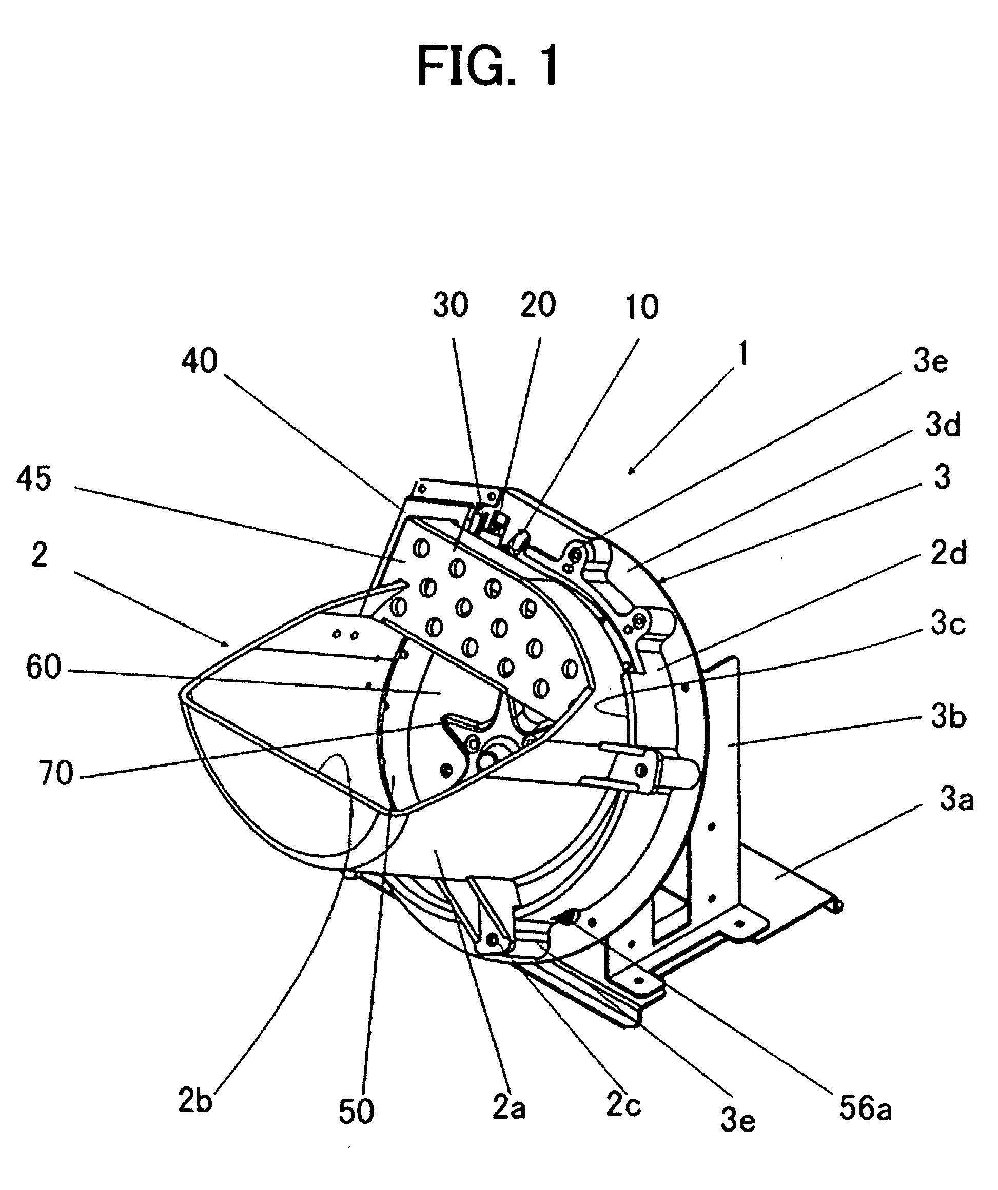
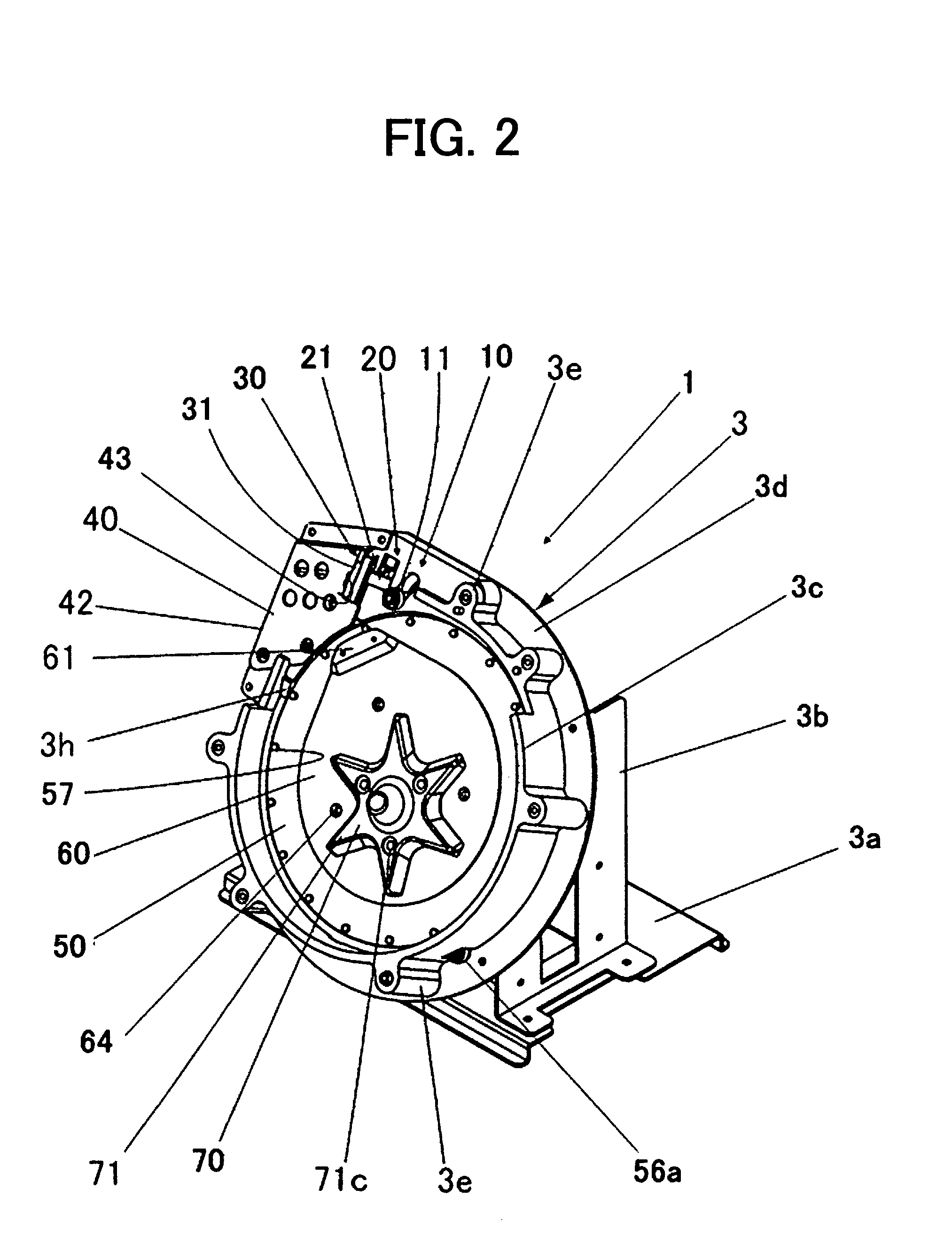
[0060]FIG. 1 is a perspective view showing a whole of the coin hopper according to Embodiment 1 of the present invention.

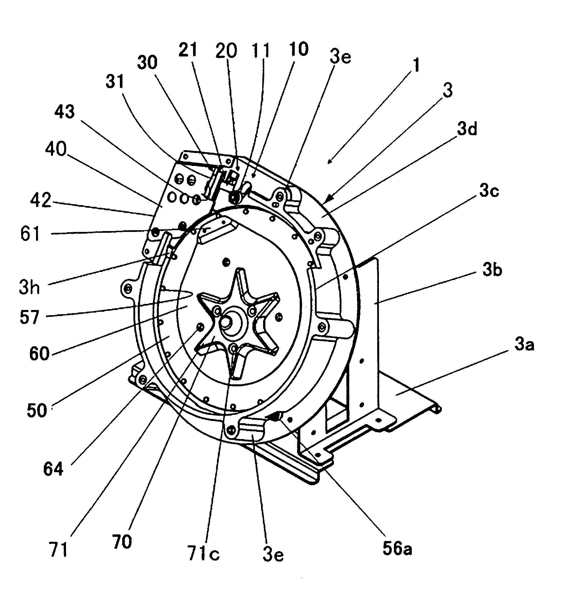
[0061] As shown in FIG. 1, the coin hopper 1 according to Embodiment 1 of the present invention has a hopper bowl 2 for storing a plurality of coins in bulk stacked state, and a main body 3 of the hopper for supporting and fixing the hopper bowl 2 in an upwardly inclined state.

[0062] Furthermore, the hopper bowl 2 has a hopper head section 2a which is projected in a forward direction than the main body 3 of the hopper and has a configuration having an increasing deepness and being inclined toward the agitator 70, a coin inlet port 2b for allowing the coins in an upward direction, a projection section 2c for the attachment and fixture on the main body 3 of the hopper 3, and an fitting body sect...

embodiment 2

[0147] Next, by referring to FIGS. 11 through 14, Embodiment 2 of the present invention will be explained. The same structure as Embodiment 1 will be denoted by the same reference numeral. Incidentally, the basic structure of the present invention is the same as the structure of Embodiment 1 which has been explained by using FIGS. 1 through 10. Consequently, since an explanation on the basic structure explicated in Embodiment will be overlapped, the explanation on the basic structure will be omitted with respect to Embodiment 2.

[0148]FIG. 11 is a view showing a transmission mechanism of Embodiment 2 in the coin hopper 1.

[0149] Embodiment 2 shown in FIG. 11 comprises a rotary disc 50 for dispensing coins one by one with a plurality of coin anchor pins 57 arranged in a predetermined distance, a transmission inner tooth gear 52, a drive gear 82, a transmission gear 83, and a one way-clutch 100 for preventing a reverse of the axis 84.

[0150]FIG. 12 is a broken view of the one-way clut...


PUM


Abstract

The invention promotes a smooth agitation and efficient transport of coins by setting the rotation direction of the agitator in the same direction as the rotary disc to move a center of rotation of the agitator to a location where most coins are collected.

Description

FIELD OF THE INVENTION [0001] The present invention relates to a coin hopper which is used for dispensing coins stored in a coin bowl in bulk. Incidentally, the coins include officially current coins, substitute coins such as medals and tokens for game machines, and similar coins. BACKGROUND OF THE INVENTION [0002] Conventionally, various types of apparatus are known as apparatus for dispensing disc-like coins. [0003] For example, patent document 1 discloses an apparatus in which a stack wheel is provided on the front of a top section of a pinwheel, a plurality of pins are provided on the circumference of the pinwheel between a circumferential section of the pinwheel and a circumferential section of the stack wheel in a radial manner. Furthermore an agitator shown in such a manner that the agitator shown in the drawings which has three projections is anchored on a central section of the stack wheel to agitate the coins in the hopper. [0004] This apparatus is constituted in such a ma...

Claims


Application Information

Patent Timeline
Patent Type & Authority Applications(United States)
IPC IPC(8): G07D1/00G07D9/00
CPCG07D9/008G07D1/00G07D2201/00
Inventor ABE, HIROSHIINOZUKA, TAKASHI
Owner ASAHI SEIKO CO LTD
Why Eureka
Try Eureka