Radio frequency identification tag inlay sortation and assembly

a radio frequency identification and tag inlay technology, applied in the field of circuit assembly and test, can solve the problems of difficult testing before or after lamination process, affecting the quality of radio frequency identification tags,

Active Publication Date: 2005-07-21
SYMBOL TECH LLC
View PDF50 Cites 72 Cited by
  • Summary
  • Abstract
  • Description
  • Claims
  • Application Information

AI Technical Summary

Benefits of technology

[0013] In an example embodiment, an infeed magazine contains a stack of assembled tags (e.g., antennas and dies). A tag carrier receives a tag from the infeed magazine. A testing station receives the tag from the tag carrier and tests the received tag. The test...

Problems solved by technology

Testing before or after the lamination process is difficult when the tags are in a web format, where tags are formed in an array of tags, typ...

Method used


Image

  • Radio frequency identification tag inlay sortation and assembly
  • Radio frequency identification tag inlay sortation and assembly
  • Radio frequency identification tag inlay sortation and assembly

Examples


example combined

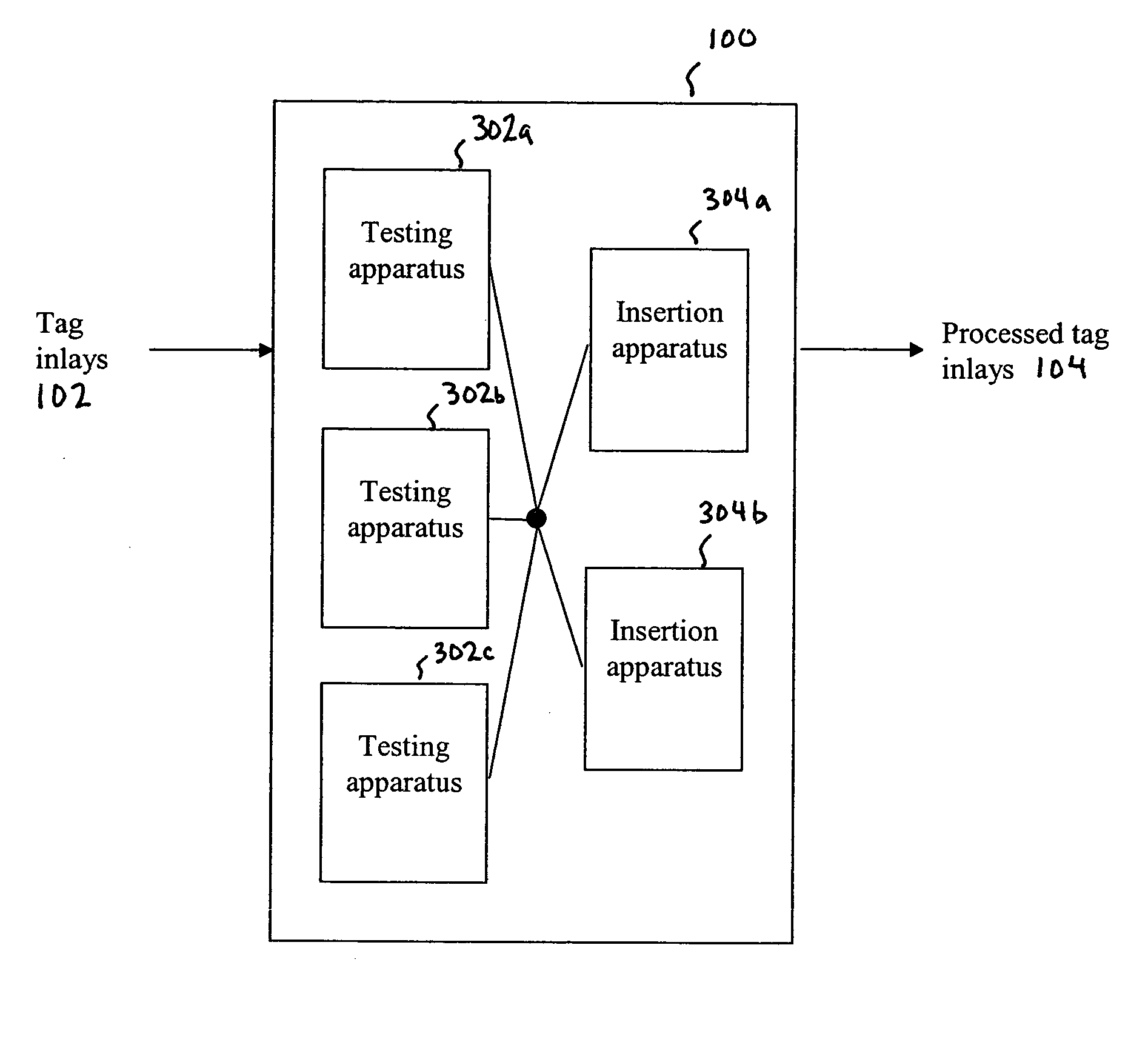
Inlay Testing and Processing Embodiments

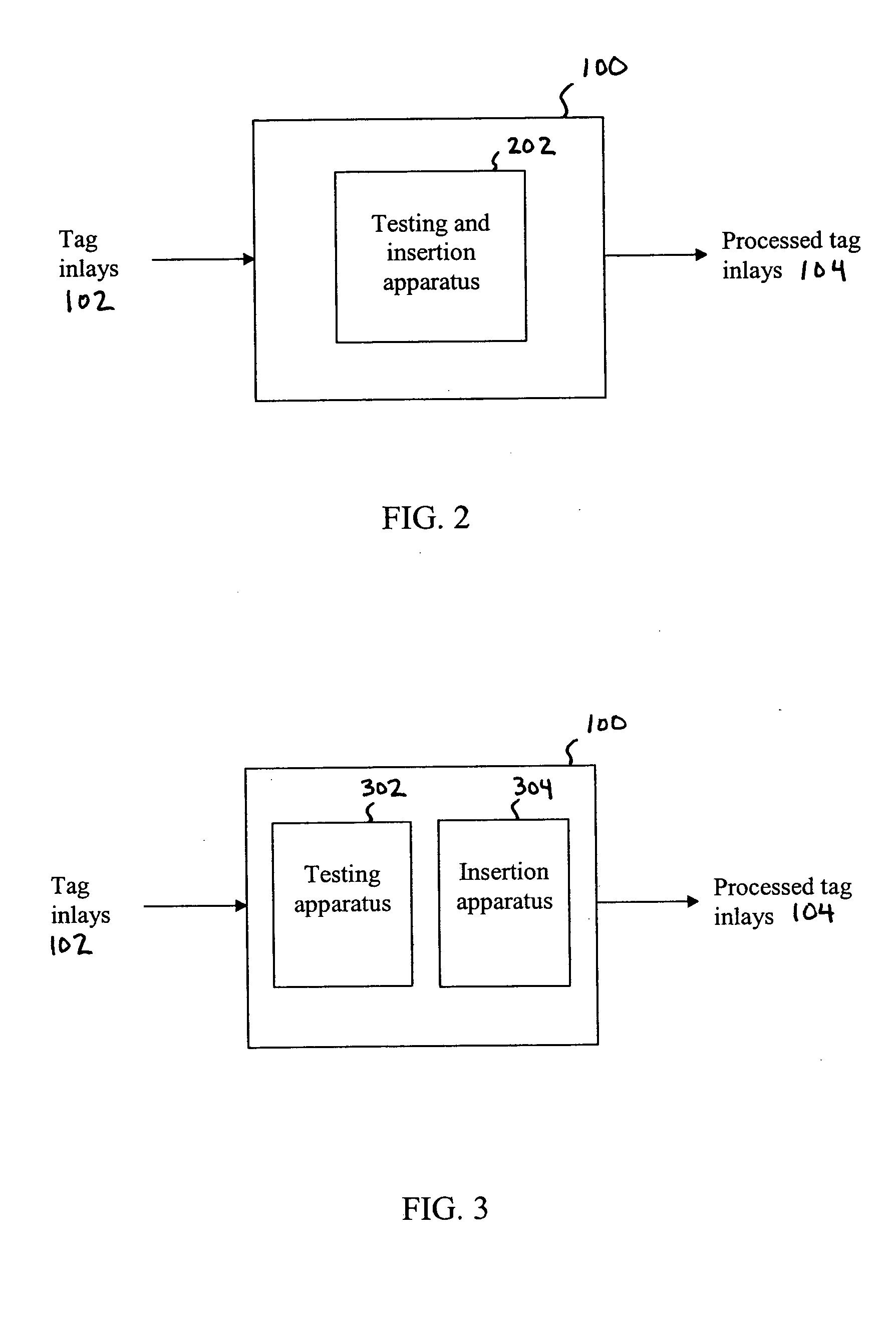
[0063]FIGS. 10A and 10B show front and side views, respectively, of an example tag inlay sorter and applicator system 1000, according to an embodiment of the present invention. For example, system 1000 is an example of testing and insertion apparatus 202, shown in FIG. 2. System 1000 tests and sorts pre-cut (e.g., singulated) RFID tag inlays and accurately applies them to a die cut adhesive region on one of three backing liners. System 1000 outputs RFID tag inlays formed into pressure sensitive labels, appropriate for dispensing with standard labeling equipment. The embodiment of FIGS. 10A and 10B enables high production speeds and precision placement of tag inlays.

[0064] System 1000 receives RFID tag antenna inlays that are pre-cut and stacked, and receives rolls of pressure sensitive adhesive on a liner. The rolls typically have pressure sensitive adhesive formed in regions (e.g., rectangular areas) on the liner, where tag inlays are to be ...


PUM

PropertyMeasurementUnit
Sensitivityaaaaaaaaaa
Transport propertiesaaaaaaaaaa

Abstract

A method, system, and apparatus for a radio frequency identification (RFID) tag inlay tester and sorter system are described. A tag inlay is received. A characteristic of the tag inlay is tested. The tag inlay is disposed if the tag inlay is determined to fail the test of characteristic. The tag inlay is transported to a processing station if the tag inlay is determined to have passed the test of characteristic. The tag inlay is processed at the processing station. In an aspect, the tag inlay testing and tag inlay processing is performed in a single apparatus. In an alternative aspect, the tag inlay testing is performed by a first apparatus, and the tag inlay processing is performed by a second apparatus.

Description

[0001] This application claims the benefit of U.S. Provisional Application No. 60 / 535,489, filed Jan. 12, 2004, which is incorporated herein by reference in its entirety.BACKGROUND OF THE INVENTION [0002] 1. Field of the Invention [0003] The present invention relates to circuit assembly and test, and more particularly to high volume sortation of radio frequency identification (RFID) tags. [0004] 2. Background Art [0005] An RFID tag may be affixed to an item whose presence is to be detected and / or monitored. The presence of an RFID tag, and therefore the presence of the item to which the tag is affixed, may be checked and monitored by devices known as “readers.”[0006] Currently, RFID tags are assembled and then laminated to the face sheet of a pressure sensitive laminate. Once laminated, the backside of the RFID tag is coated with an adhesive, and a release liner is applied. After the release liner is applied, the tag is printed and / or die cut into the desired form factor. [0007] A t...

Claims


Application Information

Patent Timeline
IPC IPC(8): G01R1/00G06K19/07G06K19/077
CPCG01R31/2822G06K7/0095G06K19/07Y10T29/49004G06K19/07718G06K19/07749G06K19/0723
Inventor EASTIN, DAVID
Owner SYMBOL TECH LLC
Why Eureka
Try Eureka