Ejector cycle and ejector device
a technology of ejector cycle and ejector device, which is applied in the direction of fluid circulation arrangement, refrigerating machine, lighting and heating apparatus, etc., can solve the problems of insufficient heating operation, insufficient amount of refrigerant, and insufficient cooling performance, and achieve low fluid resistance
- Summary
- Abstract
- Description
- Claims
- Application Information
AI Technical Summary
Benefits of technology
Problems solved by technology
Method used
Image

Examples
first embodiment
(First Embodiment)
[0045] The embodiments of the present invention will be described hereunder with reference to the accompanying drawings.
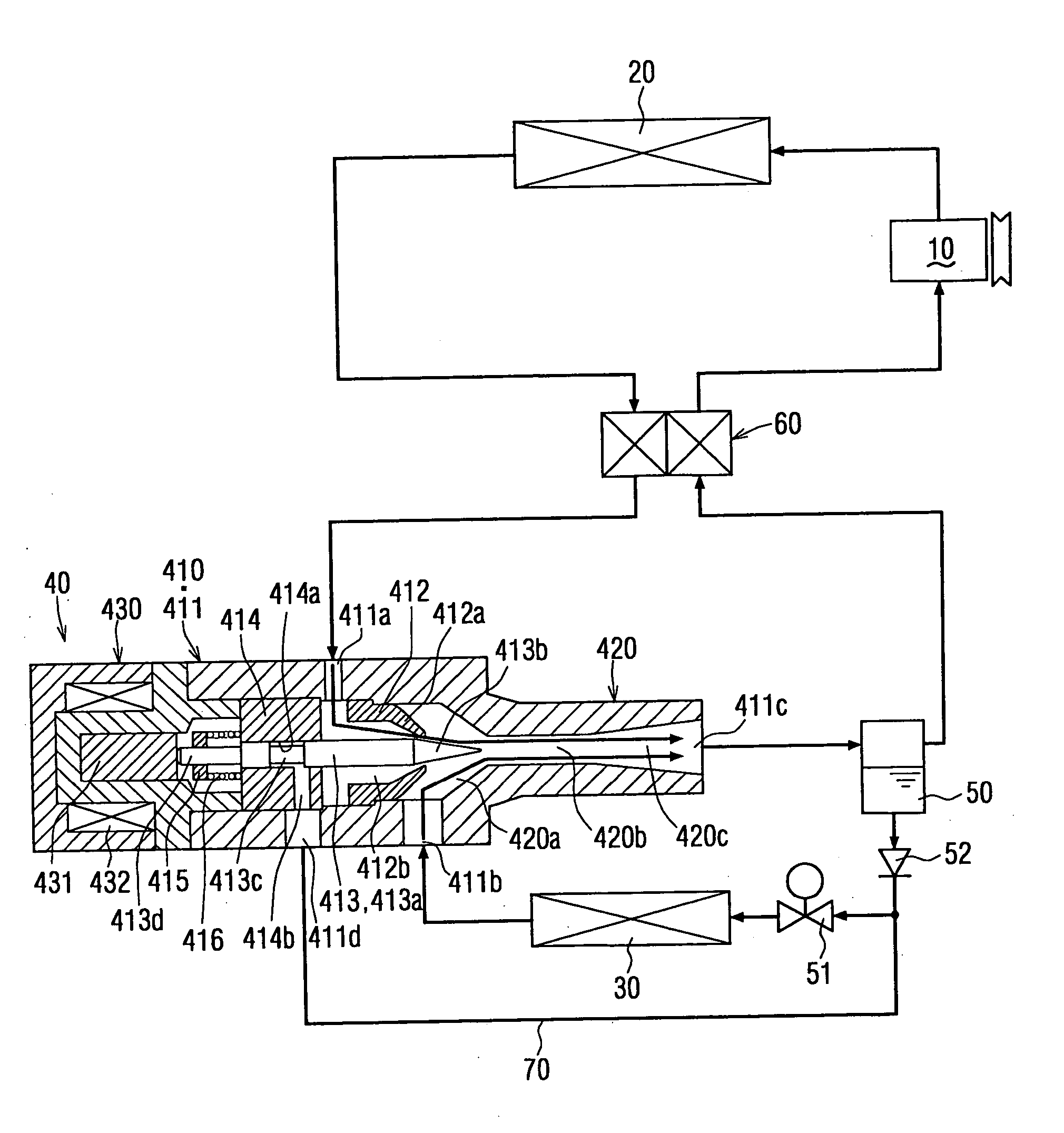
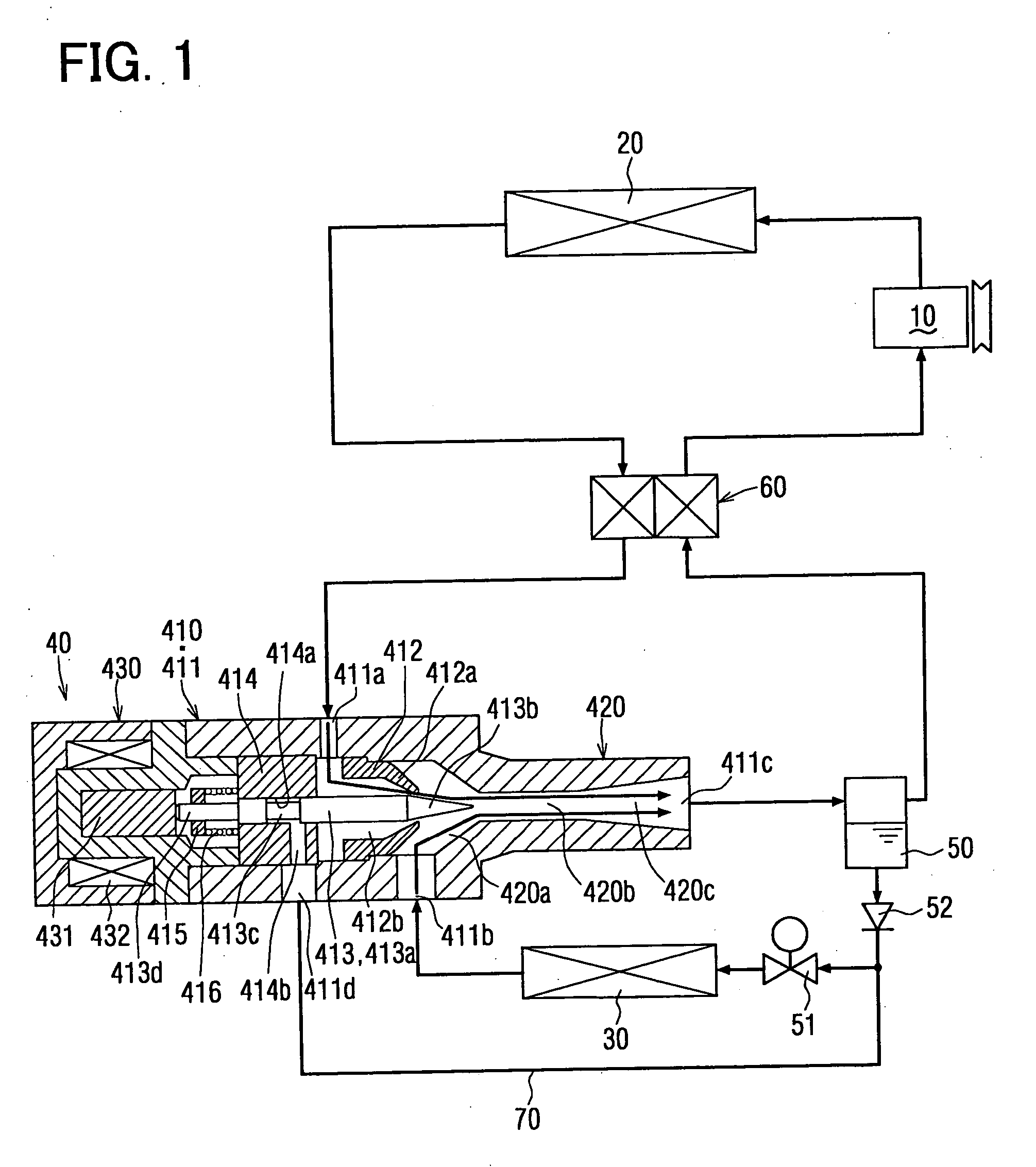
[0046]FIG. 1 shows an ejector cycle used in a cooling apparatus, according to a first embodiment of the present invention, in which the ejector cycle is operated in a cooling operation;
[0047] A numeral 10 designates a compressor driven by a driving source, such as an electric motor, for sucking and compressing refrigerant. A numeral 20 designates an outside heat exchanger for cooling down the refrigerant by heat exchanging the high-temperature and high-pressure refrigerant from the compressor 10 with outside air. A numeral 30 designates a heat exchanger for the cooling operation (also referred to as an evaporator) for absorbing heat from the air around the evaporator 30, by evaporating liquid-phase refrigerant and thereby heat exchanging the liquid-phase refrigerant with the air. And a numeral 40 designates an ejector for depressurizing and expa...
second embodiment
(Second Embodiment)
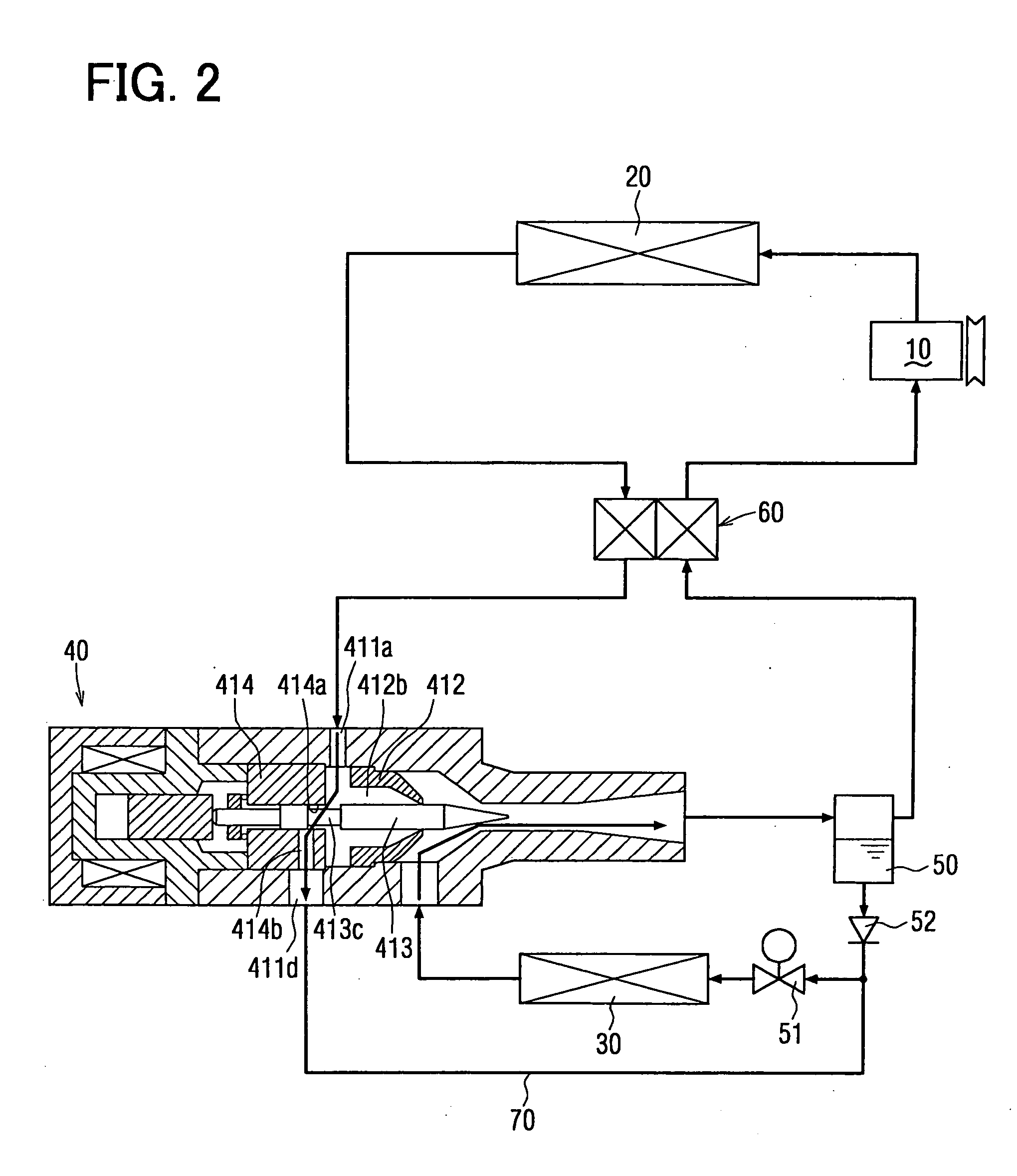
[0072] A second embodiment of the present invention will be explained with reference to FIGS. 3A to 4B, which differs from the first embodiment in that a second passage changeover means (a second movable valve 417) is provided in the ejector 40 and thereby the bypass passage 70 and the check valve 52 can be omitted in the second embodiment.
[0073] A second bypass channel 414c is formed in the common ejector body 411, so that the second bypass channel 414c is communicated at its one end with the first bypass channel 414b and at the other end with the suction port 411b. A second movable valve 417 is inserted in the second bypass channel 414c and movable therein in the longitudinal direction. A coil spring 418a is disposed in an end of the second bypass channel 414c. The second movable valve 417 has a first hole 417a to form a first communication passage, which communicates an inlet and outlet sides of the suction port 411b at a valve position shown in FIG. 3B (This ...
third embodiment
(Third Embodiment)
[0083] A third embodiment of the present invention will be explained with reference to FIGS. 5A to 7B, which differs from the second embodiment in that the ejector cycle and the ejector of the second embodiment are applied to the heat pump air-conditioning apparatus, so that a heating operation can be can be obtained.
[0084] In the third embodiment, a heat exchanger (heat radiating device) 80 for a heating operation and a depressurizing valve 81 are provided between the compressor 10 and the outside heat exchanger 20, as shown in FIG. 5A. The other components for the ejector cycle and the structure of the ejector 40 are identical to those shown in FIGS. 3A to 4B.
(A Normal Cooling Operation)
[0085] The refrigerant from the compressor 10 flows through the heat exchanger 80 (the first heat exchanger) and the outside heat exchanger 20 (the second heat exchanger) to the ejector 40. The refrigerant is then ejected through the ejector nozzle 412 and the refrigerant is s...
PUM
 Abstract
Description
Claims
Application Information
 - R&D
- Intellectual Property
- Life Sciences
- Materials
- Tech Scout
- Unparalleled Data Quality
- Higher Quality Content
- 60% Fewer Hallucinations
Browse by: Latest US Patents, China's latest patents, Technical Efficacy Thesaurus, Application Domain, Technology Topic, Popular Technical Reports.
© 2025 PatSnap. All rights reserved.Legal|Privacy policy|Modern Slavery Act Transparency Statement|Sitemap|About US| Contact US: help@patsnap.com