Squib

a technology of squib and squib, which is applied in the direction of pedestrian/occupant safety arrangement, electric fuzes, lighting and heating apparatus, etc., can solve the problems of increased work burden, increased cost, and increased difficulty, so as to reduce the burden of work and the cost of work, prevent any influence, and good ignition performance

Inactive Publication Date: 2005-07-21
HONDA MOTOR CO LTD
View PDF18 Cites 15 Cited by
  • Summary
  • Abstract
  • Description
  • Claims
  • Application Information

AI Technical Summary

Benefits of technology

[0028] According to the third preferred embodiment of the present invention, it is possible even more effectively to prevent any influence due to gas emitted from the first explosive being exerted upon the ignition element or upon the communication and ignition circuit.
[0029] According to the fourth preferred embodiment of the present invention, it is possible to anticipate a reduction in the burden of the work and in the cost thereof, and, along with ensuring a good ignition performance which can perform ignition at low energy, it is also possible to connect this device to the bus of the vehicle, without making any change to a passenger restraint device which is already fitted to the vehicle; in other words, this squib may be retrofitted to a currently existing passenger restraint device. According to the fifth preferred embodiment of the present invention, it is possible to keep said flammable material uniformly compressed and to maintain it in its tightly packed state.

Problems solved by technology

Due to this, it is necessary to preserve a certain empty space within the structure of the header, and accordingly the problem arises that the burden of work when processing the header is increased, and accordingly the cost is increased.
Furthermore, since the external shape of this squib is required to be the same as that of a prior art general purpose type squib, it is also necessary to make the communication and ignition circuit package as compact as possible, and accordingly the problem arises that the level of difficulty becomes very great when housing the capacitor for ignition in this package.
Yet further, in order to be able to anticipate increased reliability for ignition, it is necessary to preserve close contact between the flammable material (the explosive) and the ignition element; but, in order to do so, it becomes necessary to perform the task of pressure packing for pressing the flammable material into place, and the problem arises that, due to the shape of the circuit package, the work involved cannot be performed without an additional separate process.

Method used


Image

  • Squib
  • Squib
  • Squib

Examples


Embodiment Construction

[0043] In the following, the first preferred embodiment of the present invention will be explained with reference to FIGS. 1 through 4.

[0044] It should be understood that the squib according to this first preferred embodiment is most suitable for use in a protective device for persons riding in a vehicle, such as in an air bag device or a pre-tensioner device or the like which is mounted to, for example, an automobile. In the following, by way of example, the explanation will be made for the case of a protective device for persons riding in a vehicle incorporating this squib according to the first preferred embodiment being mounted to an automobile.

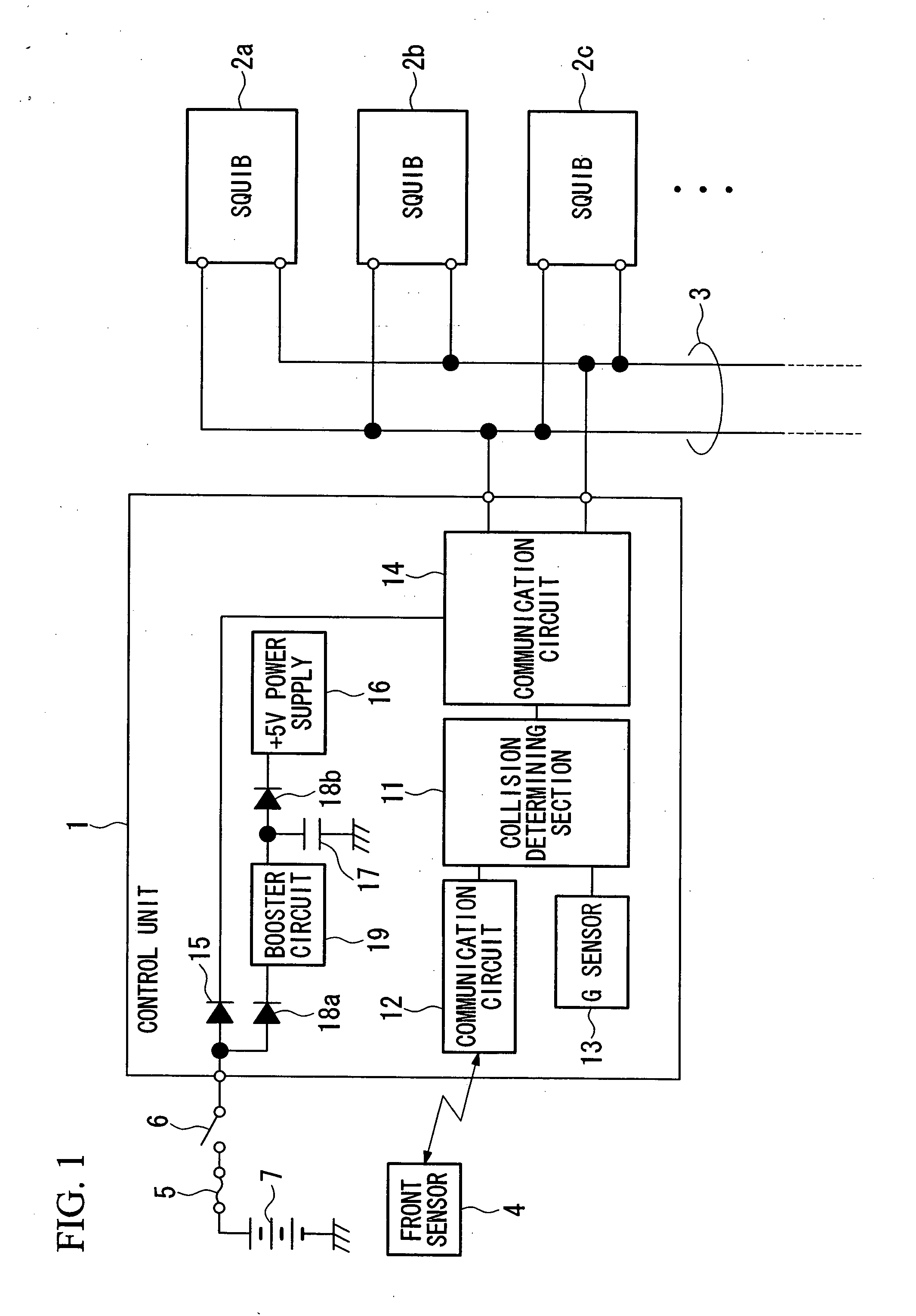
[0045] Referring to FIG. 1, the control unit 1 is a control section which constitutes the central portion of a passenger protective device which protects persons riding in the vehicle from any collision in which the vehicle is involved, and squibs 2a, 2b, 2c, . . . of a plurality of auxiliary restraint devices (not shown in the figures)...


PUM


Abstract

A squib for bus connection includes a communication and ignition unit which is connected via a pin to a bus line and is received within an inner cap, along with a quantity of a first explosive which does not emit corrosive gas. Furthermore, between this inner cap and an outer cap in which it is received, there is charged a quantity of a second explosive which is of a different type from the first explosive, the second explosive being of a type which is used in a squib in a conventional inflator.

Description

BACKGROUND OF THE INVENTION [0001] 1. Field of the Invention [0002] Priority is claimed on Japanese Patent Application No. 2003-379873, filed Nov. 10, 2003, and Japanese Patent Application No. 2003-419479, filed Dec. 17, 2003, the contents of which are incorporated herein by reference. [0003] The present invention relates to a squib (an ignition apparatus) which is used in a system which employs explosive, such as, for example, an air bag device or a pretensioner apparatus for an automobile, and particularly relates to a squib which incorporates an ignition element which can be ignited with low energy. [0004] 2. Background Art [0005] Occupant protection apparatuses such as pretensioner apparatuses and airbag apparatuses that are mounted in automobiles operate by being ignited by a squib (i.e., an ignition apparatus) in which a gas generating agent is contained in an inflator, and high pressure gas that is generated by the combustion thereof is introduced into an airbag or the like. ...

Claims


Application Information

Patent Timeline
Patent Type & Authority Applications(United States)
IPC IPC(8): B60R21/01B60R21/26F42B3/12F42D1/05
CPCB60R21/017F42D1/05F42B3/121B60R2021/26029
Inventor MATSUDA, KAZUOSAITO, KAZUTAKAMIYAKE, ETSUYANISHIMURA, JUNICHIAIDA, HIROMI
Owner HONDA MOTOR CO LTD
Why Eureka
Try Eureka