

Fluid collecting device
a technology of collecting device and mud bucket, which is applied in the direction of drilling rods, drilling pipes, drilling holes/well accessories, etc., can solve the problems of large actuators that have to be used, dangerous for personnel, and it is not possible to deploy separate mud buckets during the spinning function, so as to achieve the effect of increasing the mechanical advantage of the closing actuator
- Summary
- Abstract
- Description
- Claims
- Application Information
AI Technical Summary
Benefits of technology
Problems solved by technology
Method used
Image

Examples
first embodiment
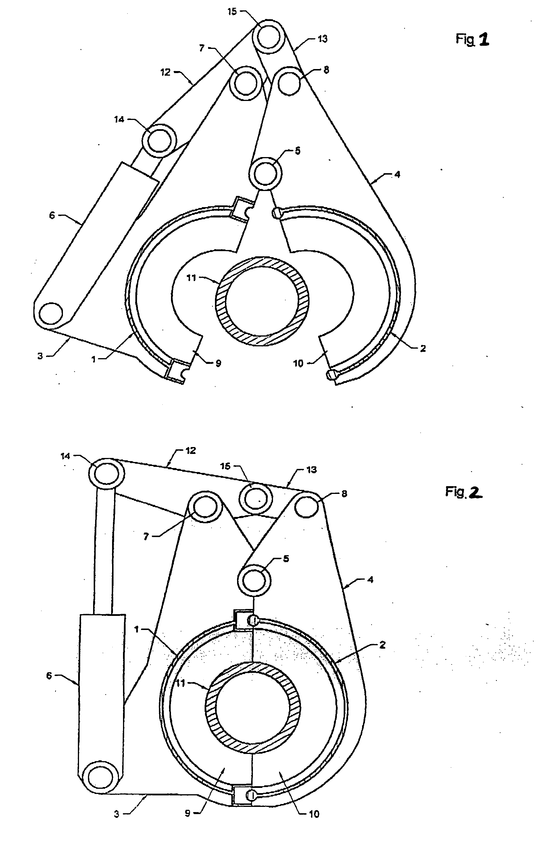
[0035] Turning to FIG. 1, the invention includes two shells 1 and 2 with bottom halves 9, 10 attached respectively thereto and with the shells fitted with arms 3 and 4 which are hinged at a common pivot point 5. An actuator 6 operates a bellcrank 12 through a pin 14. The bellcrank 12 is pivoted at pin 7 on arm 3. The bellcrank 12 is further connected to a linking member 13 by a pin 15. The linking member 13 is connected to arm 4 via pin 8.
[0036] Turning to FIG. 2, when the first embodiment is employed in a closed position around a drill pipe, the angle between the bellcrank 12 and the linking member 13 is significantly less than when the first embodiment is in the open position. Since the force available to close the adjustable fluid collecting device varies inversely with the tangent of half the angle between the bellcrank 12 and the linking member 13, a large closing force can be generated by a relatively low powered actuator. For example, if the angle between the bellcrank 12 and...
second embodiment
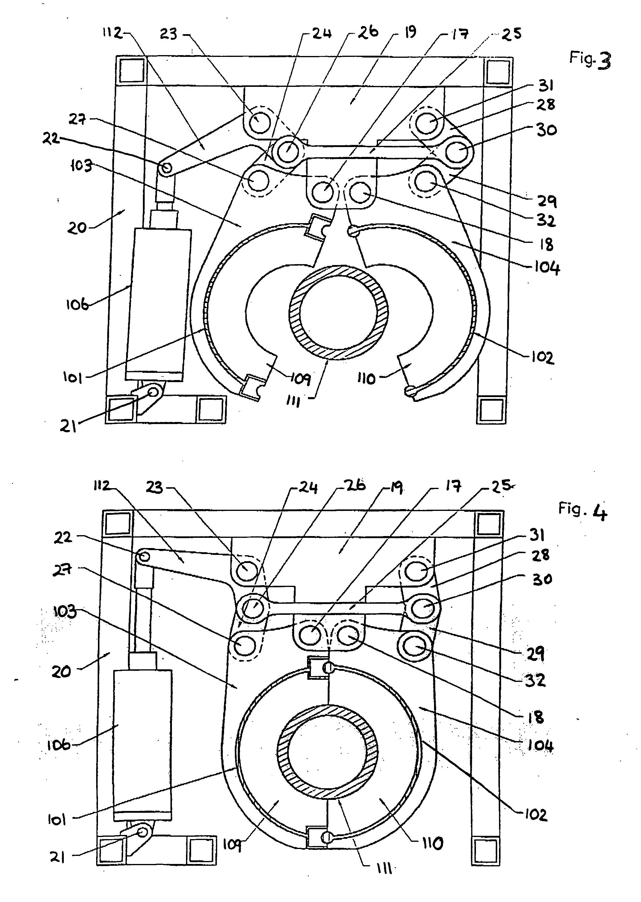
[0037] the adjustable fluid collecting device is illustrated in FIG. 3. Shells 101 and 102 with bottom halves 9, 10 are fitted with arms 103 and 104 and pivoted on pins 17 and 18 mounted on a bracket 19. An actuator 106 is attached to a rigid frame 20 by a pin 21 and operates a bellcrank 112 via a pin 22. The bellcrank 112 is attached to bracket 19 by a pin 23, and to linking members 24 and 25 by a pin 26. The other end of linking member 24 is attached to the arm 103 by a pin 27. Linking member 25 is connected to linking members 28 and 29 by pin 30. The other end of linking member 28 is attached to bracket 19 by pin 31. The other end of linking member 29 is attached to arm 104 by pin 32. Linking members 24, 28 and 29 are arranged in length such that movement of the bellcrank 112 results in equal but opposite movement of the shells 101 and 102.
[0038] As illustrated in FIG. 4, the second embodiment employs the same principal as that employed by the first embodiment: increasing the clo...
third embodiment
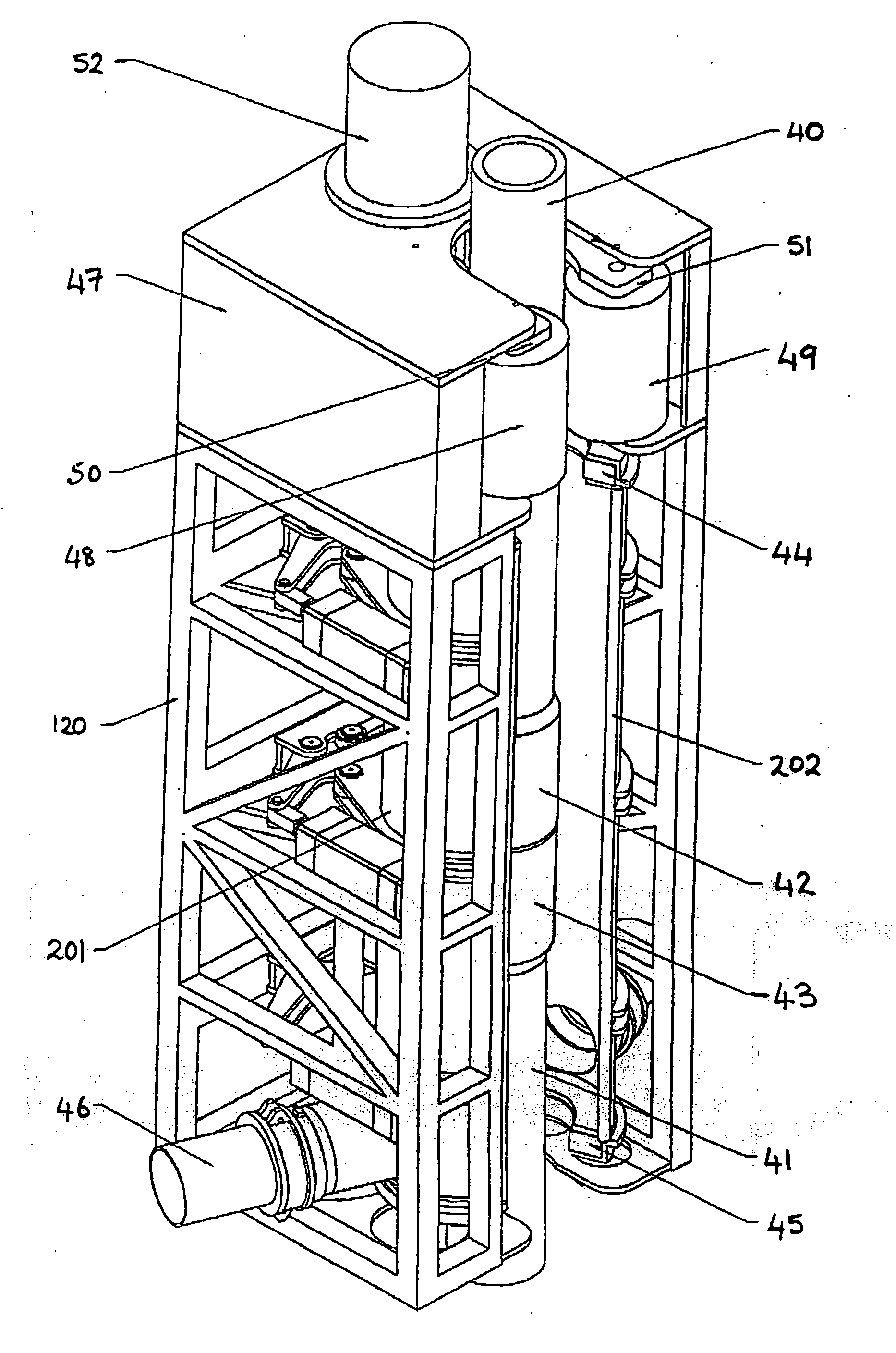
[0042] In general, the invention uses a rigid frame to support a mud bucket and facilitate the accurate operation of the mud bucket relative to the frame, thereby making it easier to deploy the mud bucket automatically by a remote linkage so that the mud bucket is safer to install.
[0043] The third embodiment of the invention also improves the safety of the operation of a mud bucket by ensuring that the operation of the device is enclosed within the rigid frame, thereby physically protecting operators from the mud bucket. To this end, the rigid frame may also be provided with suitable guarding to enhance safety. Furthermore, the frame can serve as a means of mounting a joint for a spinner.
[0044] A fourth embodiment of the invention combines a pipe spinner with the adjustable fluid collecting device of either the first or second embodiments of the invention, housed within a common mounting suitably adapted to withstand the forces involved in the operation of the pipe spinner and adju...
PUM
 Abstract
Description
Claims
Application Information