Method and apparatus for subsurface fluid sampling

a technology of subsurface fluid and method, applied in the direction of fluid removal, survey, borehole/well accessories, etc., can solve the problems of fluid that is generally unacceptable for hydrocarbon fluid sampling and/or evaluation, difficult to avoid contamination, and various challenges

Inactive Publication Date: 2005-07-21
SCHLUMBERGER TECH CORP
View PDF47 Cites 57 Cited by
  • Summary
  • Abstract
  • Description
  • Claims
  • Application Information

AI Technical Summary

Benefits of technology

[0014] Another aspect of the invention relates to a downhole tool useful for extracting virgin fluid from a subsurface formation penetrated by a wellbore surrounded by contaminated fluid. The apparatus comprises a probe, a contamination monitor and a controller. The probe is positionable in fluid communication with the formation and adapted to flow the fluids from the formation into the downhole tool. The probe has a wall therein defining a first channel and a second channel. The contamination monitor is adapted to measure fluid parameters in at least one of the channels. The controller is adapted to receive data from the contamination monitor and send command signals in response thereto whereby the wall is selectively adjusted within the probe to optimize the flow of the virgin fluid through the first channel and into the downhole tool.
[0015] Another aspect of the invention relates to a downhole tool useful for extracting virgin fluid from a subsurface f...

Problems solved by technology

Various challenges may arise in the process of obtaining virgin fluid from subsurface formations.
This material often contaminates the virgin fluid as it passes through the borehole, resulting in fluid that is generally unacceptable for hydrocarbon fluid sampling and/or evaluation.
Such fluid is referred to herein as “contaminated fluid.” Because fluid is sampled through the borehole, mudcake, ceme...

Method used


Image

  • Method and apparatus for subsurface fluid sampling
  • Method and apparatus for subsurface fluid sampling
  • Method and apparatus for subsurface fluid sampling

Examples


Embodiment Construction

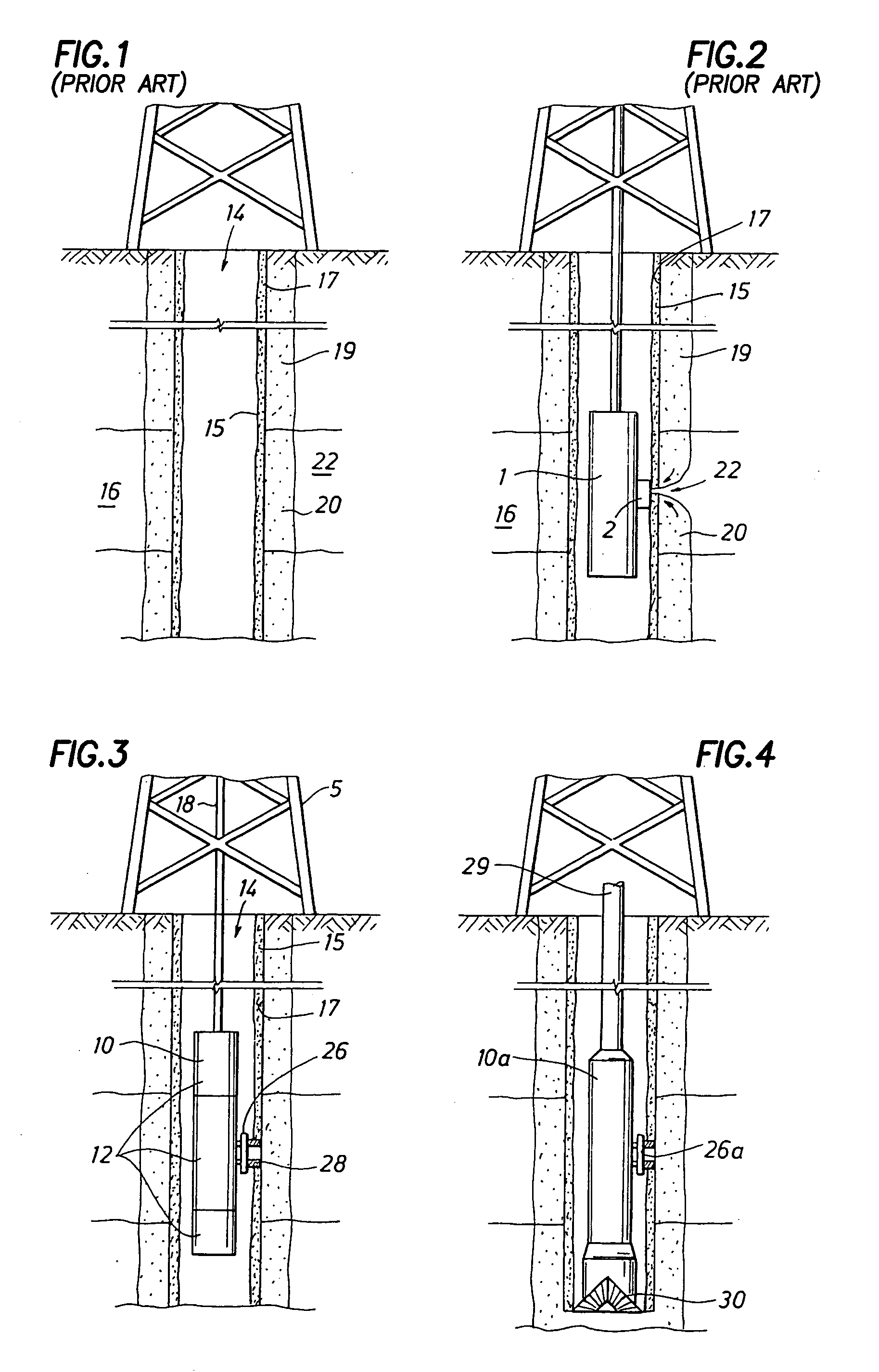
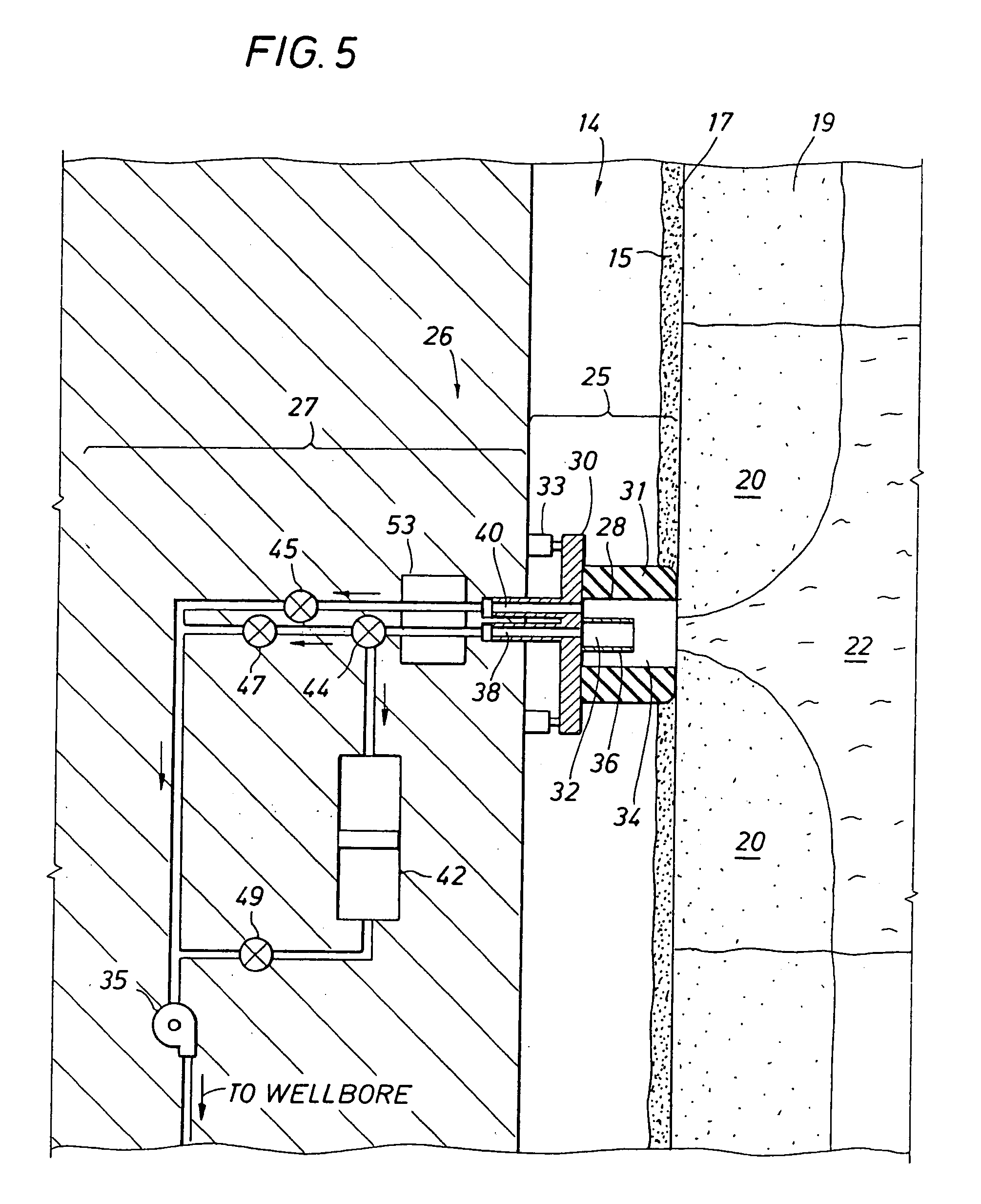
[0044] Presently preferred embodiments of the invention are shown in the above-identified figures and described in detail below. In describing the preferred embodiments, like or identical reference numerals are used to identify common or similar elements. The figures are not necessarily to scale and certain features and certain views of the figures may be shown exaggerated in scale or in schematic in the interest of clarity and conciseness.

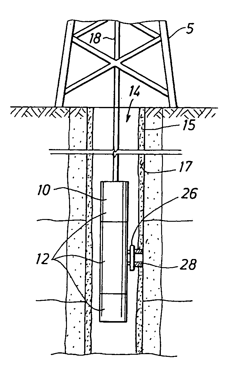
[0045] Referring to FIG. 3, an example environment within which the present invention may be used is shown. In the illustrated example, the present invention is carried by a down hole tool 10. An example commercially available tool 10 is the Modular Formation Dynamics Tester (MDT) by Schlumberger Corporation, the assignee of the present application and further depicted, for example, in U.S. Pat. Nos. 4,936,139 and 4,860,581 hereby incorporated by reference herein in their entireties.

[0046] The downhole tool 10 is deployable into bore hole 14 and...


PUM


Abstract

An apparatus and method for extracting fluid from a subsurface formation is disclosed. A downhole sampling tool is provided with a probe having an internal wall capable of selectively diverting virgin fluids into one or more virgin flow channels for sampling, while diverting contaminated fluids into one or more contaminated flow channels to be discarded. The characteristics of the fluid passing through the channels of the probe may also be measured using techniques, such as optical density, to evaluate various fluid parameters, such as contamination levels. The data generated during sampling may be sent to a controller capable of generating data, communicating and/or sending command signals. The flow of fluid into the downhole tool may be selectively adjusted to optimize the flow of fluid into the channels by adjusting the internal wall within the probe and/or by adjusting the flow rates through the channels. The configuration of the internal wall and/or the flow rates may be automatically adjusted by the controller and/or manually manipulated to further optimize the fluid flow.

Description

TECHNICAL FIELD [0001] The invention relates to apparatus and methods for collecting fluid samples from subsurface formations. BACKGROUND OF THE INVENTION [0002] The collection and sampling of underground fluids contained in subsurface formations is well known. In the petroleum exploration and recovery industries, for example, samples of formation fluids are collected and analyzed for various purposes, such as to determine the existence, composition and producibility of subsurface hydrocarbon fluid reservoirs. This aspect of the exploration and recovery process can be crucial in developing drilling strategies and impacts significant financial expenditures and savings. [0003] To conduct valid fluid analysis, the fluid obtained from the subsurface formation should possess sufficient purity, or be virgin fluid, to adequately represent the fluid contained in the formation. As used herein, and in the other sections of this patent, the terms “virgin fluid”, “acceptable virgin fluid” and v...

Claims


Application Information

Patent Timeline
IPC IPC(8): E21B49/08E21B49/10
CPCE21B49/10E21B49/08
Inventor HILL, BUNKER M.ZAZOVOSKY, ALEXANDER
Owner SCHLUMBERGER TECH CORP
Why Eureka
Try Eureka