
Method of making high performance heat sinks

a heat sink and high-performance technology, applied in the direction of lighting and heating apparatus, paper/cardboard containers, semiconductor/solid-state device details, etc., can solve the problem of undisturbed open portion of the fin, and achieve the effect of different size, shape and function

Inactive Publication Date: 2005-07-21
COOLIT SYSTEMS INC
View PDF25 Cites 18 Cited by
  • Summary
  • Abstract
  • Description
  • Claims
  • Application Information

AI Technical Summary

Benefits of technology

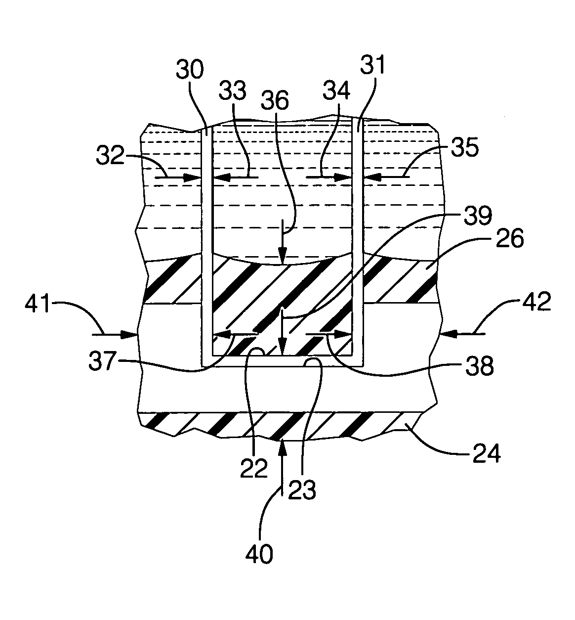
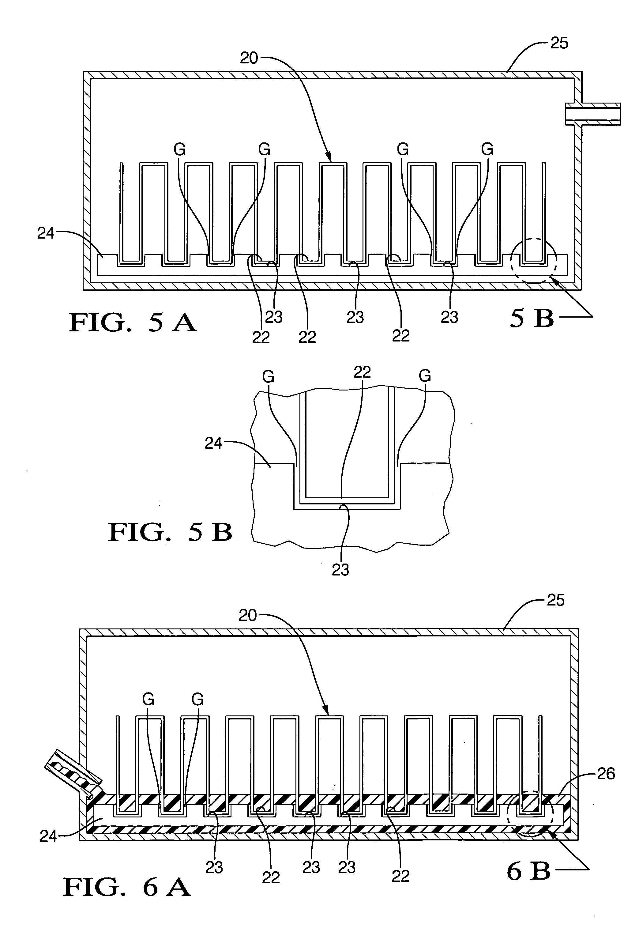
[0019] As disclosed, a closely spaced array of thin, corrugated fins is nested so as to place their lower crests directly within the grooves in the otherwise solid base plate, with no intermediate braze material, adhesive, or other mechanical fastener at the fin to groove interface. Then, the assembly is placed in an evacuated chamber, removing substantially all air from the fin to base plate groove interfaces. Next, a localized, targeted hermetical seal material is applied at, and, as far as the fins are involved, only at, the interfaces between the fins and grooves, filling the interiors of the fin crests, and the intervening spaces between the fin walls, to a level slightly above the surface of the base plate. This seals the gaps between the fin crests and the base plate grooves. That portion of the fins extending above the sealed crests (above base plate upper surface) is left open and unsupported. The seal material is compressible, not rigid, but is significantly different in size, shape and function from the kind of all encompassing, unitary, evacuatable sleeve that is conventionally used. This localized fin to groove interface seal may be provided, for example, by a poured in place fill of a water soluble elastomeric coating, such as polyvinyl alcohol (PVA), which fills the relatively wide interior of the fin crests, but which is too viscous to flow into the much narrower interfaces between the exterior of the fin crests and the grooves. After the targeted seal is applied, the fin and base plate assembly is removed from the evacuated chamber. The seal, while not evacuated per se, as a sleeve is, still protects the sealed interface from air entry. Then, the sealed sub assembly is subjected to the same type of isostatic pressure apparatus described above, at a pressure exceeding the room temperature yield strength of the fin and base plate material, at the relatively cool temperatures typically utilized in the CIP process. The omni directionally acting fluid does not crush the fins, as it would if acting on a surrounding sleeve, but instead surrounds and intersperses between the fins, acting equally in all directions. Just as an open container is not crushed under deep water, so the open portion of the fins are undisturbed. At the sealed interface, however, the pressurized fluid, which is prevented from entering the fin to groove interfaces, instead presses on the seal material. The seal material inside the fin crests transfers pressure to the fin-groove interfaces, deforming the fin crests plastically into an intimate, mechanical bonding relationship with the grooves within which they are seated. The seal material may then be removed by stripping or dissolution in a solvent such as water. If required, the assembly may then be heat treated to form even stronger, diffusion type metallurgical bonds between the fins and the base plate.

Problems solved by technology

Just as an open container is not crushed under deep water, so the open portion of the fins are undisturbed.

Method used


Image

  • Method of making high performance heat sinks
  • Method of making high performance heat sinks
  • Method of making high performance heat sinks

Examples


Embodiment Construction

[0031]FIG. 5 is a view of a heat sink pre assembly (not yet fully formed) with a folded comprised of a generally rectangular or U shaped folded fin 20 having a plurality of lower crests 22, which are nested in rectangular grooves 23 in a base plate 24. The crest 22 can be considered the short fold between fin walls and a short portion of the integral fin wall to either side thereof, having a basic U shape. This nesting would be done so as to create minimal gaps “G” between the exterior surfaces of the crests 22 and the interior surfaces of the base plate grooves 23, as by a controlled, close press fit. While shown exaggerated for purposes of illustration, no press fit can fully close the gaps g sufficiently to create a sufficiently intimate, solid interface for efficient heat conduction. This fin-plate pre assembly is placed in an evacuatable “glove box”25, so named because hermetic gloves or the like can be used to manipulate work pieces inside the box without jeopardizing the seal...


PUM

PropertyMeasurementUnit
temperature yield strengthaaaaaaaaaa
yield strengthaaaaaaaaaa
temperature yield strengthaaaaaaaaaa

Abstract

A method of heat sink manufacture in which the crests of a conductive fin are nested down into close fitting grooves in a flat, conductive base plate, with small interface gaps G. A compressive material is set inside the fin crests and the grooves, viscous enough to not intrude into the gaps G, to a level sufficient to substantially fill the grooves. The work piece thus created is subjected to a cold hydrostatic oil bath, crushing the outer surfaces of the fin crests into the internal surfaces of the grooves where the compressed seal covers, while the rest of the fin is supported against net deformation by the surrounding oil.

Description

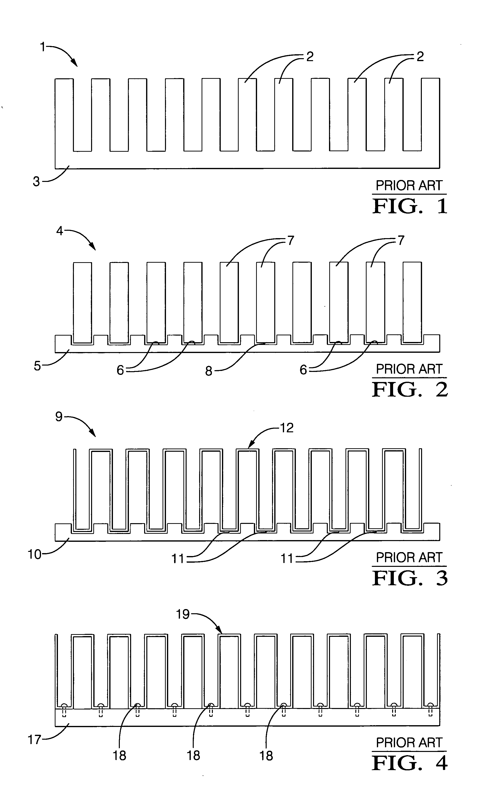
[0001] A method is disclosed for making heat sinks with a plurality of elongated, separately formed, densely arrayed fins affixed to a base plate. An intimate mechanical bond between the fins and the base plate is achieved by the plastic deformation of the fins at room temperature in a cold isostatic press (CIP). FIELD OF THE INVENTION [0002] The subject invention relates to fabrication of cooling assemblies such as heat sinks for dissipating heat generated by electronic or non-electronic devices. BACKGROUND OF THE INVENTION [0003] Basically a heat sink is a heat-dissipating device comprising an array of elongated or pin fins affixed to one side of a base plate. Affixed to the other side of the base plate is a heat source such as a computer chip. The heat generated by the heat source is removed from the base plate by a fluid that is either stagnant or flowing over the base plate through the fin array. The stagnant fluid removes heat from the fins and the base plate by natural convec...

Claims


Application Information

Patent Timeline
Patent Type & Authority Applications(United States)
IPC IPC(8): B23K1/00F28F3/02H01L21/48H01L23/367
CPCB23P2700/10F28D2021/0029F28F3/025H01L21/4882Y10T156/10H01L2924/0002H01L23/3672H01L2924/00
Inventor BHATTI, MOHINDER SINGHGRIFFIN, PATRICK MITCHELL
Owner COOLIT SYSTEMS INC
Learn More