Pop-up striker

a pop-up striker and spherical technology, applied in the field of pop-up strikers, can solve the problems of between the lid and the body, fingers can barely grasp the clearance for opening the lid completely, and achieve the effect of reducing noise emission

Inactive Publication Date: 2005-07-21
KEYKERT USA
View PDF12 Cites 23 Cited by
  • Summary
  • Abstract
  • Description
  • Claims
  • Application Information

AI Technical Summary

Benefits of technology

[0017] In a further preferred embodiment a damper restrains the pivoti

Problems solved by technology

The resulting clearance between the lid and the body is in general very small, s

Method used


Image

  • Pop-up striker
  • Pop-up striker
  • Pop-up striker

Examples


Embodiment Construction

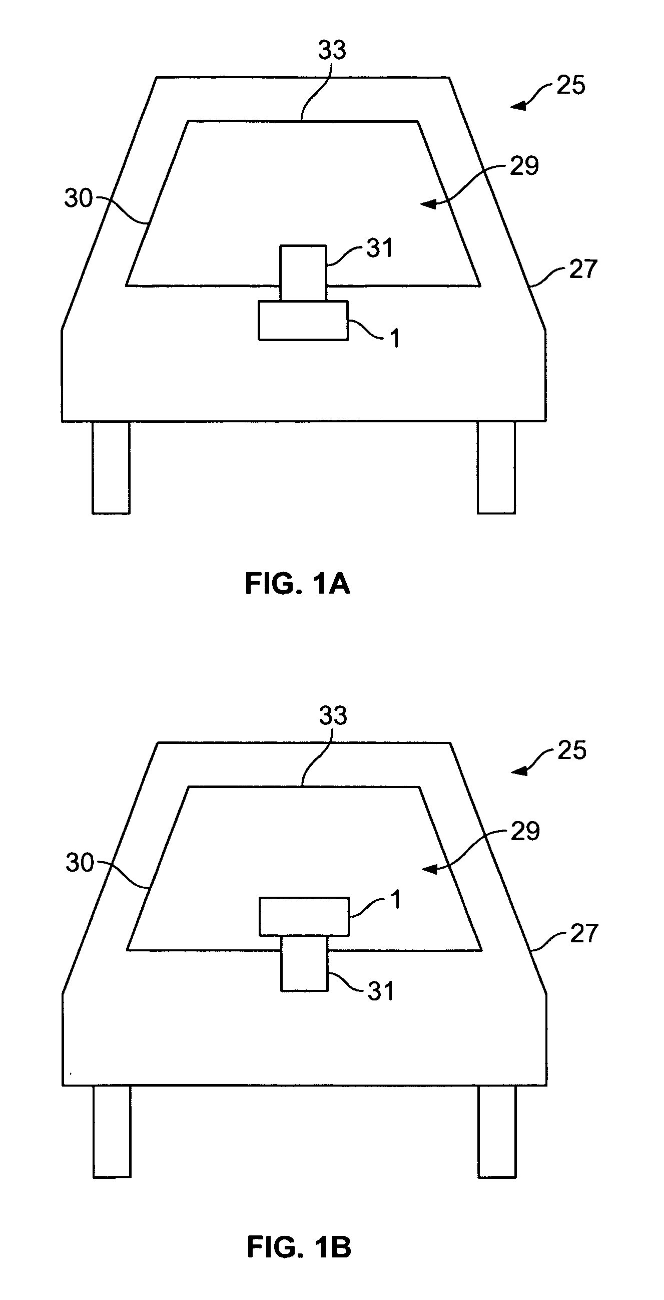
[0025]FIG. 1A shows schematically a rearview on a vehicle 25 with a decklid 29 for closing an opening 30 of a body 27 of the vehicle 25. The decklid 29 is pivoted to the body 27 at a pivot axis 33 such that the decklid 29 can be opened in an upward direction. The decklid 29 comprises a previously known locking element 31 for locking the decklid to the body 27 which comprises a pop-up striker 1 for raising the decklid 29 from the body 27, after the decklid 29 has been unlocked.

[0026]FIG. 1B shows schematically a rearview on a vehicle 25 whereby the decklid 29 comprises the pop-up striker 1 and the body 27 comprises the locking element 31.

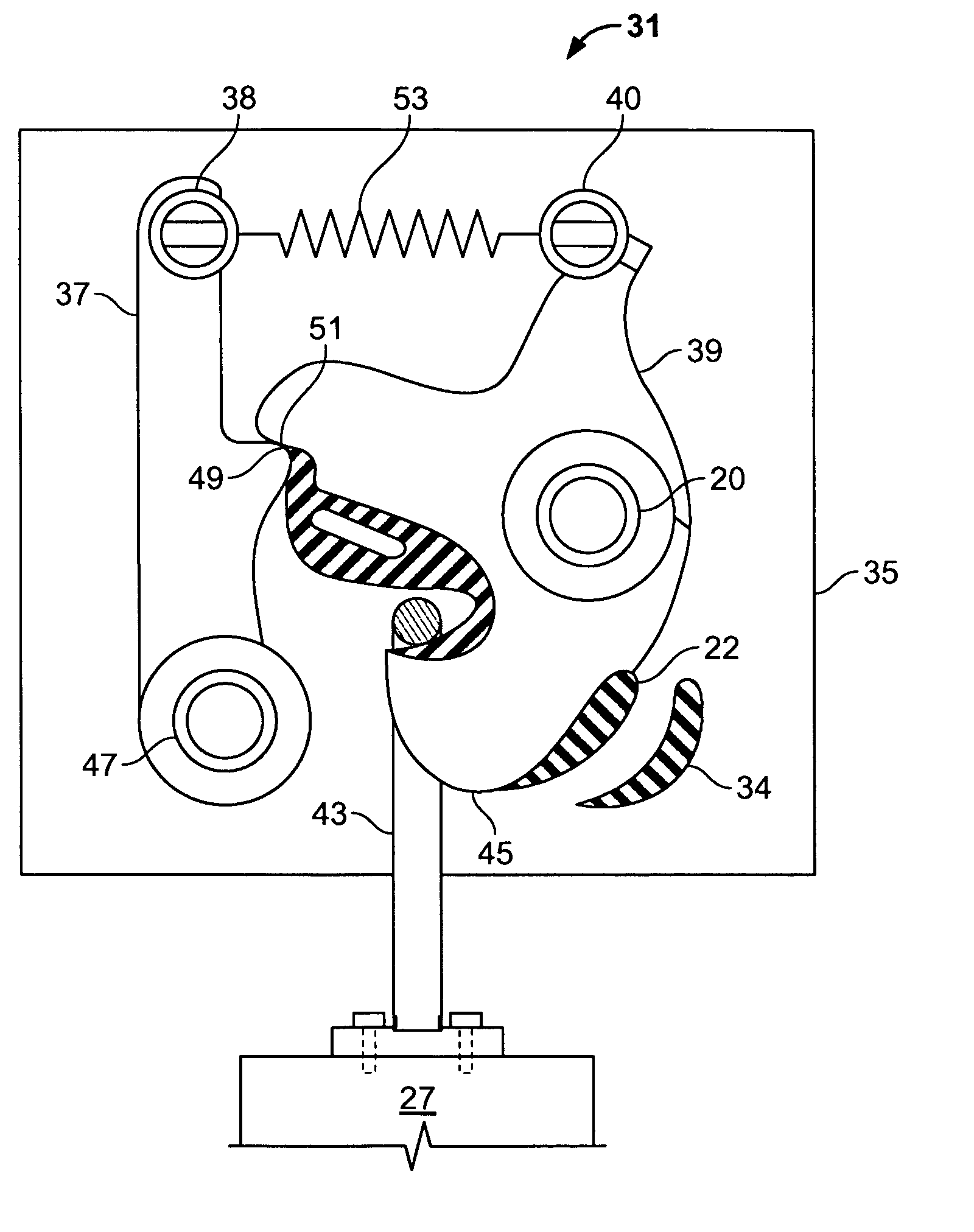
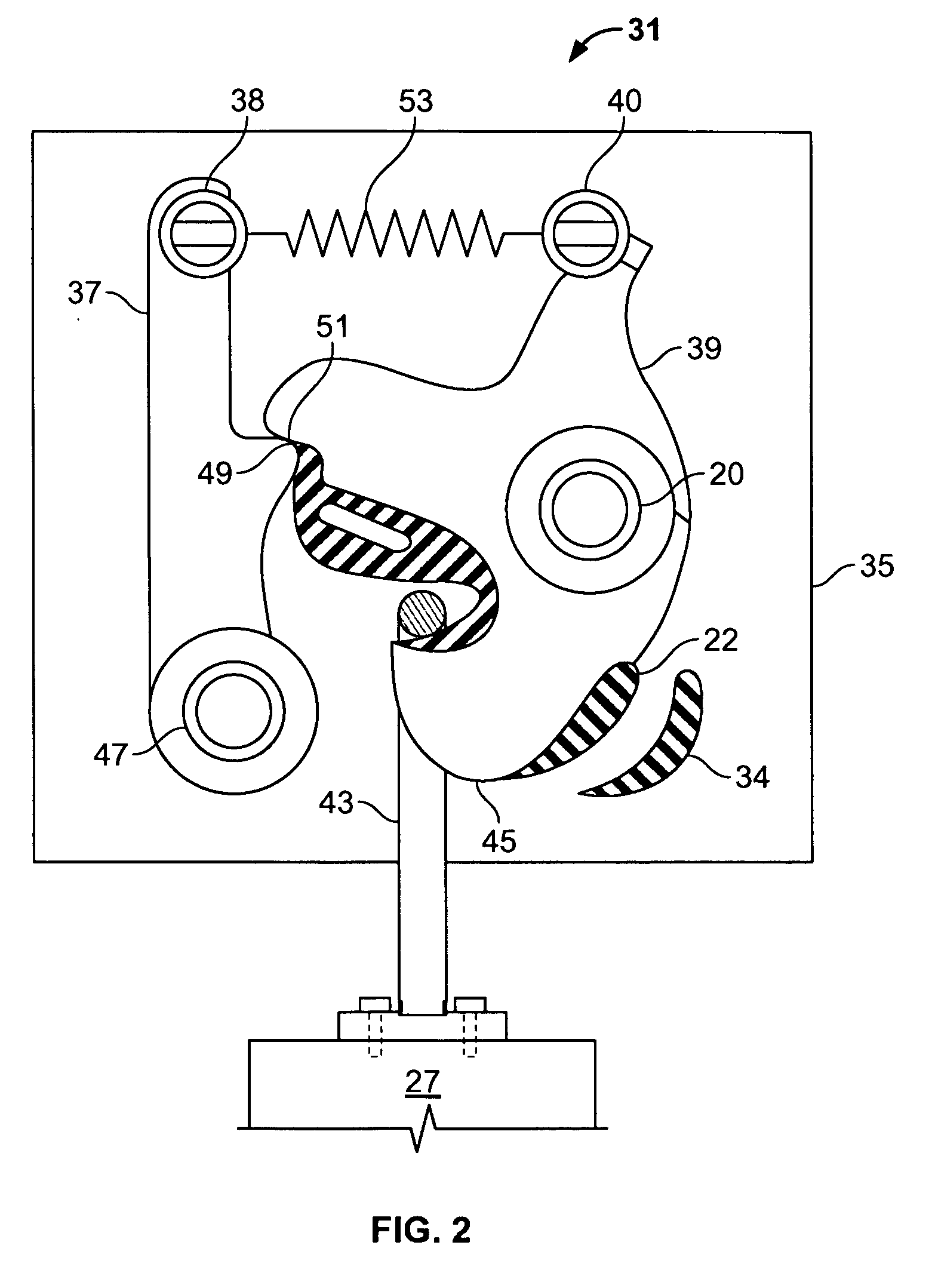
[0027] A typical locking element 31 is schematically shown in FIG. 2 together with a prior art locking striker 43. The locking element 31 comprises a catch 39 and a pawl 37 and interacts with a locking striker 43. The locking striker 43 is secured to the body 27, whereas the catch 39 and the pawl 37 are rotatably mounted on a latch frame plate 35, ...


PUM


Abstract

A pop-up striker for raising a lid, like a decklid, hood or door, of a vehicle comprises a spring for providing a pop-up force, whereby a first end of the spring is attached to a base plate. The pop-up striker further comprises a pop-up lever, which is pivoted to the base plate, whereby the pop-up lever is engaged with a second end of the spring. A striker element is secured to the base plate to restrict a pivoting movement of the pop-up lever.

Description

[0001] This application claims the benefit of U.S. Provisional Application No. 60 / 513,605, filed Oct. 24, 2003, which is herein incorporated by reference in its entirety.BACKGROUND [0002] 1. Field of the Invention [0003] The invention relates to a pop-up striker for raising a lid, like a decklid, which is pivoted to a body of a vehicle. [0004] 2. Background of the Invention [0005] In general a lid of a vehicle can be locked to the body of the vehicle by a locking element. This locking element may comprise a locking striker secured to the body of the vehicle and a catch with a hook part secured to the lid. For locking the lid the catch can be moved to a first position at which the hook part is in a hook engagement with the locking striker. For unlocking the lid the catch can be moved to a second position at which the hook part is in disengagement with the striker. The catch is retained in the first position by a pivoted pawl, whereby a shoulder of the pawl is in engagement with a cor...

Claims


Application Information

Patent Timeline
IPC IPC(8): B60J5/00B62D25/10B62D25/12E05B15/02E05B17/00E05B65/19
CPCE05B17/0037E05B83/16E05B77/38E05B77/42E05B85/045
Inventor BISHOP, BRYANSURATKAL, VASANTHUDRISTE, DANIELVIGDORCHIK, SIMON
Owner KEYKERT USA
Why Eureka
Try Eureka