System, apparatus, and method for conducting electromagnetic induction surveys

Inactive Publication Date: 2005-07-21
SCHLUMBERGER TECH CORP
View PDF19 Cites 39 Cited by
  • Summary
  • Abstract
  • Description
  • Claims
  • Application Information

AI Technical Summary

Benefits of technology

[0030] In one aspect of the invention, a method is provided for conducting an electromagnetic induction survey of a geological formation penetrated by a borehole lined with a conductive casing. The method includes positioning a transmitter in the borehole, whereby the transmitter generates a transmitter magnetic moment, and positioning a distant receiver external of the borehole to detect a magnetic field induced by the transmitter, whereby the distant receiver is disposed across part of the formation from the borehole. Furthermore, an auxiliary receiver is positioned in the borehole proximate the transmitter to detect a magnetic field induced by the transmitter and attenuated by the conductive casing. Subsequently, a first casing attenuation factor that is applicable to the magnetic field measured by the auxiliary receiver is determined from a ratio of the measured magneti

Problems solved by technology

The conductive tubular liners interfere with resistivity measurements and are difficult and costly to remove from the borehole once they are installed.
As a result, prior art systems such as that shown in FIG. 1 are not suitable for analyzing hydrocarbon reservoirs once extraction of the hydrocarbons begins.
Any inaccurate correction for the conductive liner properties would have an enormous impact on the accuracy of the “corrected field.” Furthermore, conductive

Method used


Image

  • System, apparatus, and method for conducting electromagnetic induction surveys
  • System, apparatus, and method for conducting electromagnetic induction surveys
  • System, apparatus, and method for conducting electromagnetic induction surveys

Examples


Embodiment Construction

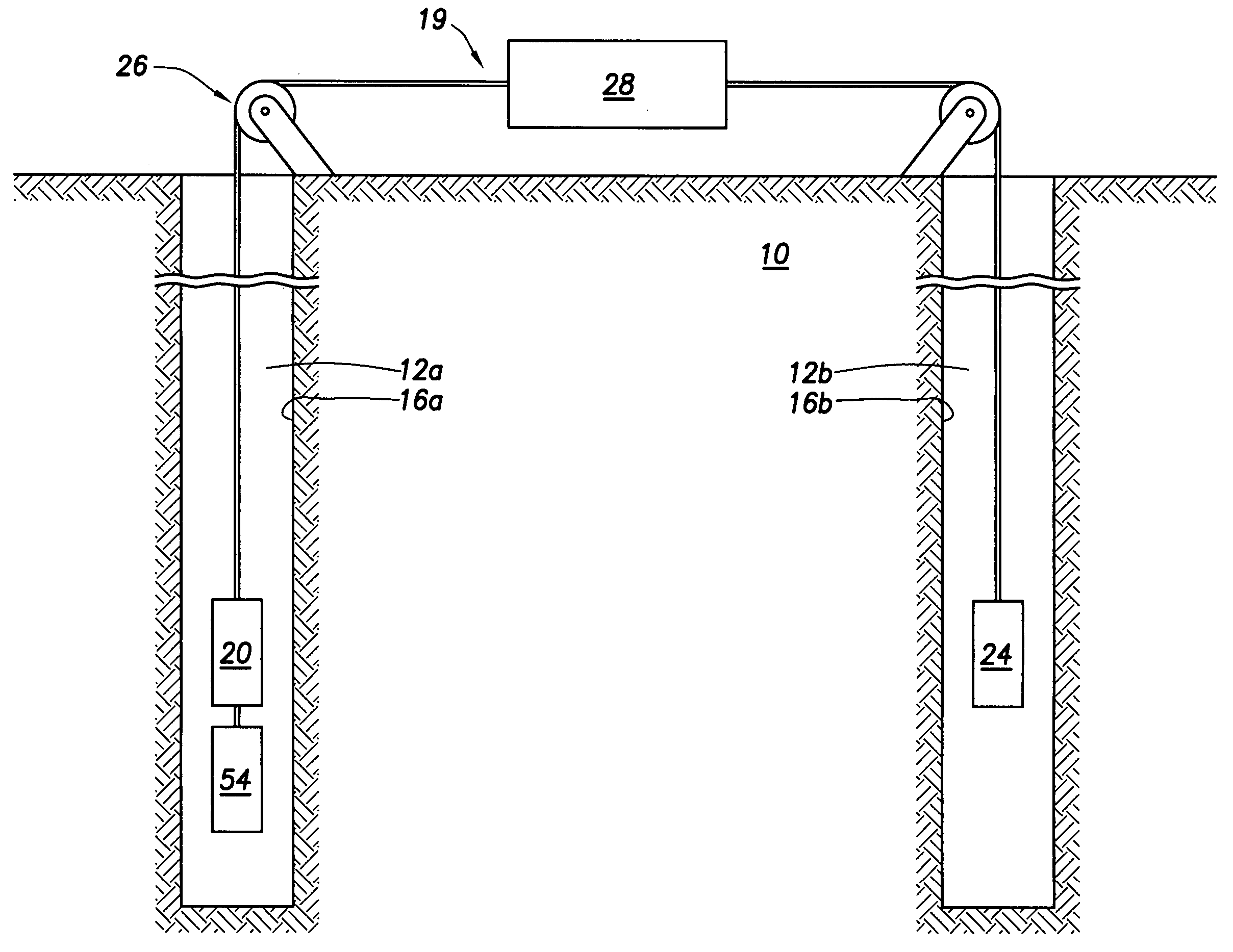
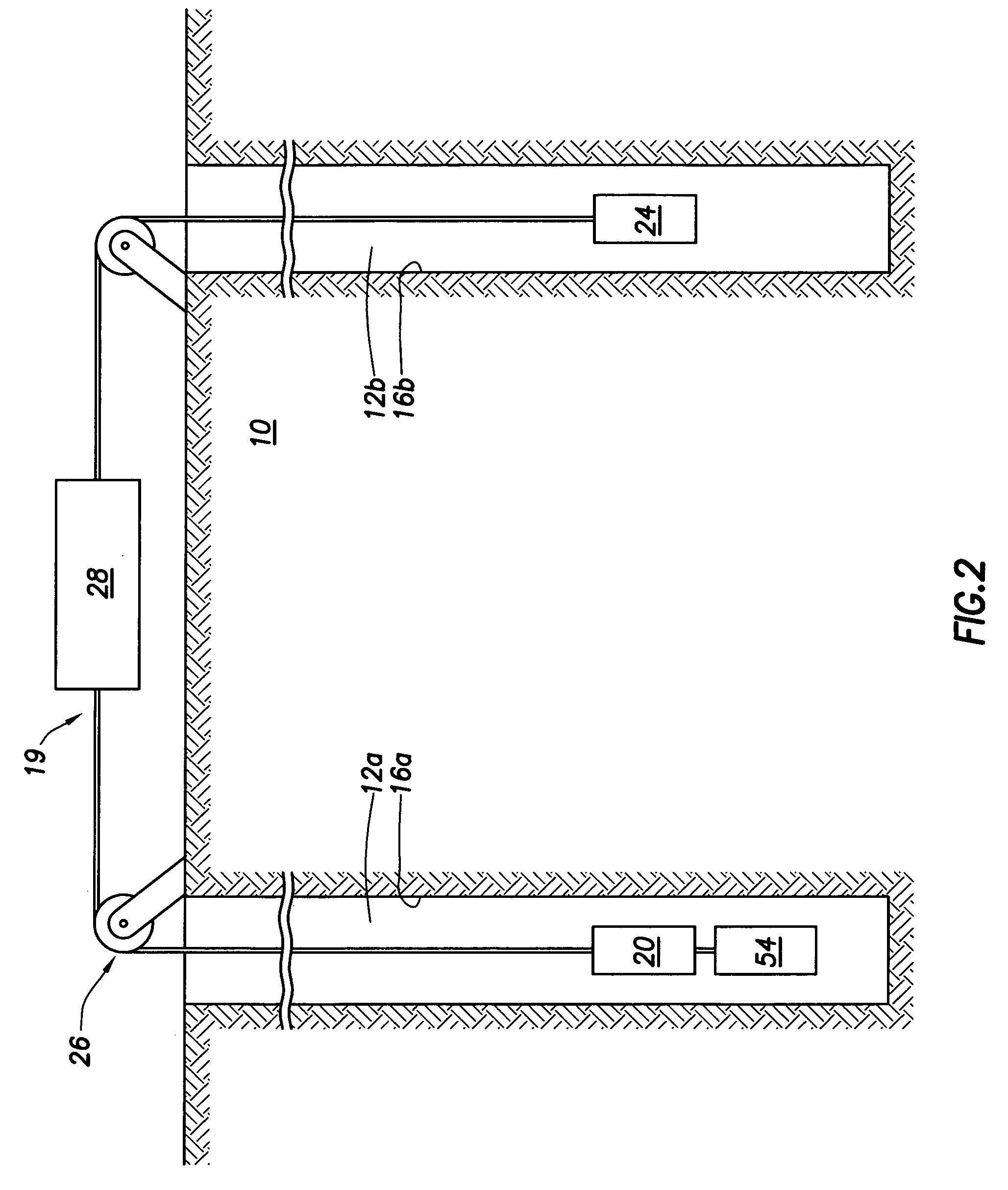
[0041] Embodiments of the present invention utilize an auxiliary receiver, an auxiliary transmitter, or both to facilitate the correction of shielding effects of conductive casings. In one embodiment, as shown in FIG. 2, a system 19 employed to analyze the geological formation 10 includes a transmitter 20 disposed in borehole 12a and a receiver 24 disposed in a borehole 12b. Alternatively, transmitter 20 and receiver 24 may be disposed in the same borehole for single borehole tomography (not shown). For purposes of the present description, system 19 may be referred to as an electromagnetic tomography system or a system for conducting electromagnetic induction surveys.

[0042] The transmitter 20 typically comprises multi-turn wires wound around a magnetically permeable (e.g., mu-metal or ferrite) core and other electronic control components (e.g., a capacitor); (not shown). The receiver 24 typically comprises more than one antenna (not shown). These antennas may point to the x, y, and...


PUM


Abstract

A method is provided for conducting an electromagnetic induction survey of a geological formation penetrated by a borehole lined with a conductive casing. The method includes positioning a transmitter in the borehole, whereby the transmitter generates a transmitter magnetic moment, and positioning a distant receiver external of the borehole to detect a magnetic field induced by the transmitter, whereby the distant receiver is disposed across part of the formation from the borehole. Furthermore, an auxiliary receiver is positioned in the borehole proximate the transmitter to detect a magnetic field induced by the transmitter and attenuated by the conductive casing. Subsequently, a first casing attenuation factor that is applicable to the magnetic field measured by the auxiliary receiver is determined from a ratio of the measured magnetic field at the auxiliary receiver and the transmitter magnetic moment. A second casing attenuation factor applicable to the measurement of the magnetic field at the distant receiver is determined from a non-linear relationship (e.g., a power law relationship) between the first casing attenuation factor and the second attenuation factor, wherein the second attenuation factor is less than the first attenuation factor. Then, a formation attenuation factor applicable to the measured magnetic field at the distant receiver is determined from a relationship between the magnetic moment of the transmitter, the second casing attenuation factor, and the measured magnetic field at the distant receiver. Finally, the method correlates the determined value of the formation attenuation factor to a resistivity characteristic of the formation between the distant receiver and the transmitter.

Description

[0001] This is a Continuation-in-Part of U.S. application Ser. No. 10 / 753,621, filed Jan. 8, 2004, which is a Divisional Application of U.S. application Ser. No. 09 / 879,252, filed Jun. 12, 2001 (which issued as U.S. Pat. No. 6,703,838), which is Continuation-in-Part of U.S. application Ser. No. 09 / 610,573 filed on Jul. 5, 2000, which is a Divisional Application of U.S. application Ser. No. 09 / 290,156 filed on Apr. 12, 1999, which claimed priority of a provisional U.S. Application Ser. No. 60 / 081,653, filed on Apr. 13, 1998 and entitled “ELECTROMAGNETIC INDUCTION METHOD AND APPARATUS FOR THE MEASUREMENT OF THE ELECTRICAL RESISTIVITY OF ROCK FORMATIONS BETWEEN DRILL HOLES CASED WITH STEEL.”FIELD OF THE INVENTION [0002] The present invention relates generally to well logging techniques using electromagnetic measurements. More particularly, the invention relates to electromagnetic induction surveys between boreholes, at least one of which includes a conductive liner. The survey method o...

Claims


Application Information

Patent Timeline
IPC IPC(8): G01V3/28
CPCG01V3/28
Inventor CONTI, UGO
Owner SCHLUMBERGER TECH CORP
Why Eureka
Try Eureka