Head polarity detection algorithm and apparatus

a head polarity and detection algorithm technology, applied in the field of data heads, can solve problems such as data errors and frequent polarity flip behavior

Inactive Publication Date: 2005-07-21
SEAGATE TECH LLC
View PDF9 Cites 58 Cited by
  • Summary
  • Abstract
  • Description
  • Claims
  • Application Information

AI Technical Summary

Problems solved by technology

However, one problem which can occur with SAF transducers is that they frequently exhibit polarity flip behavior.
Inversion of the read back signal will result in data errors.

Method used


Image

  • Head polarity detection algorithm and apparatus
  • Head polarity detection algorithm and apparatus
  • Head polarity detection algorithm and apparatus

Examples


Embodiment Construction

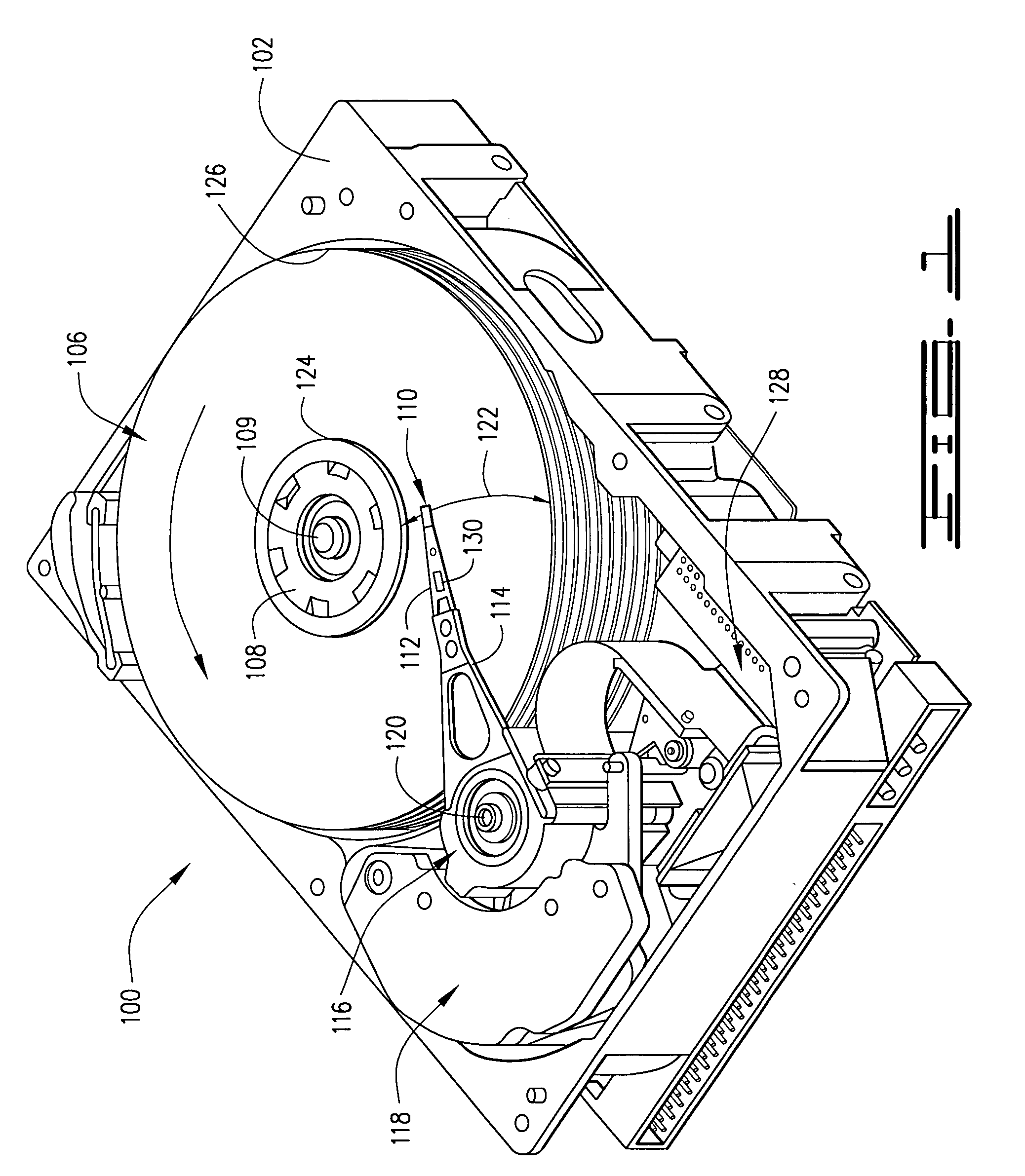
[0020]FIG. 1 is an isometric view of a disc drive 100 in which embodiments of the present invention are useful. Disc drive 100 includes a housing with a base 102 and a top cover (not shown). Disc drive 100 further includes a disc pack 106, which is mounted on a spindle motor (not shown) by a disc clamp 108. Disc pack 106 includes a plurality of individual discs, which are mounted for co-rotation about central axis 109. Each disc surface has an associated disc head slider 110 which is mounted to disc drive 100 for communication with the disc surface. In the example shown in FIG. 1, sliders 110 are supported by suspensions 112 which are in turn attached to track accessing arms 114 of an actuator 116. The actuator shown in FIG. 1 is of the type known as a rotary moving coil actuator and includes a voice coil motor (VCM), shown generally at 118. Voice coil motor 118 rotates actuator 116 with its attached heads 110 about a pivot shaft 120 to position heads 110 over a desired data track a...


PUM

PropertyMeasurementUnit
polarity detectionaaaaaaaaaa
polarityaaaaaaaaaa
timeaaaaaaaaaa

Abstract

A method of determining and monitoring head polarity of data heads comprises performing a head polarity detection routine. The head polarity detection routine comprises the step of setting a read gate period duration to a first value. The routine also comprises searching for a good address mark signal during a first read gate period with a channel polarity set to a first polarity. The routine further comprises identifying a polarity of a data head based upon the channel polarity when the good address mark is detected.

Description

FIELD OF THE INVENTION [0001] The present invention relates generally to data heads, and more particularly but not by limitation to head polarity in data heads. BACKGROUND OF THE INVENTION [0002] In data storage systems, data is recorded on a storage media, typically in data tracks. For example, in disc drive data storage systems, data is written in circular concentric data tracks on the surface(s) of one or more data storage discs. In magnetic disc drive data storage systems, advancement in material science has allowed magnetic data to be written on the media at greater track pitch per inch (TPI) densities than had previously been possible. One factor which makes recording at higher TPI densities possible is a reduction of the transducer's geometry. Synthetic anti-ferromagnetic (SAF) transducers have been used in magnetic storage systems to achieve higher TPI (for example, 130 TPI). The properties of SAF transducers have proven to provide good thermal performance, amplitude respons...

Claims


Application Information

Patent Timeline
Patent Type & Authority Applications(United States)
IPC IPC(8): G11B5/00G11B5/02G11B5/455G11B20/10G11B21/02G11B27/36
CPCG11B5/455G11B20/10009G11B2220/20G11B2005/001G11B2005/0013G11B27/36
Inventor CHIANG, TAIVIECHIANG, WINGKONGOOI, KIANKEONGYEO, KIANSOONDING, MINGZHONG
Owner SEAGATE TECH LLC
Why Eureka
Try Eureka