
Device and method for controlling the position of the latral edge of a continuous web

a technology of continuous webs and devices, which is applied in the direction of automatic control devices, precision positioning equipment, angiosperms/flowering plants, etc., can solve the problems of single edge sagging, lateral distortion of paper webs, and region-wise wave formation of paper webs, etc., to achieve high quality

Inactive Publication Date: 2005-07-21
OCE PRINTING SYST
View PDF5 Cites 16 Cited by
  • Summary
  • Abstract
  • Description
  • Claims
  • Application Information

AI Technical Summary

Benefits of technology

This solution enables quick and accurate settling of the web edge to the desired position, reducing control deviations and enhancing print quality by compensating for fraying, bending, and other irregularities, thus preventing image smearing and mechanical stress.

Problems solved by technology

If the web has no marginal perforation, then a lateral displacement of the lateral edge can occur during the transport of the web through the copier or printer owing to inhomogeneities in the web, and the print image cannot be printed in a positionally accurate way.
When guiding a paper web through a printer, lateral distortion of the paper web and a region-wise wave formation and / or single-edge sagging of the paper web can occur despite a stably running front edge of the web due to non-uniform mechanical web properties of the paper web or due to the basic setting of the various guide rollers not being exactly parallel.
Further, a single edge of the web may sag, for example, disturbing the image printing in the region of a non-contact fixing station since the sagging web section can come into contact with mechanical parts and the toner images are smeared as a result or the sagging section is subjected to an energy load that is too high.

Method used


Image

  • Device and method for controlling the position of the latral edge of a continuous web
  • Device and method for controlling the position of the latral edge of a continuous web
  • Device and method for controlling the position of the latral edge of a continuous web

Examples


Embodiment Construction

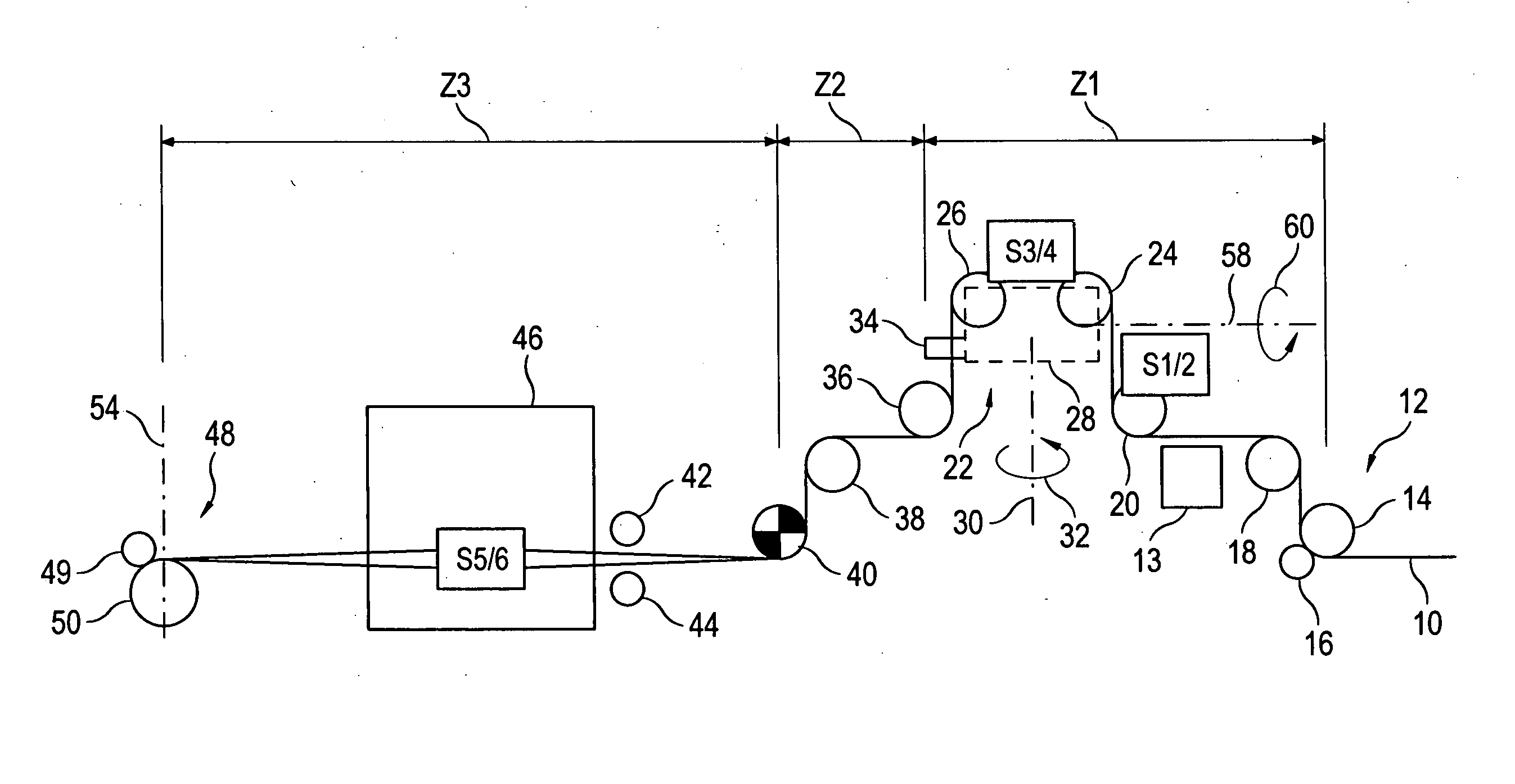
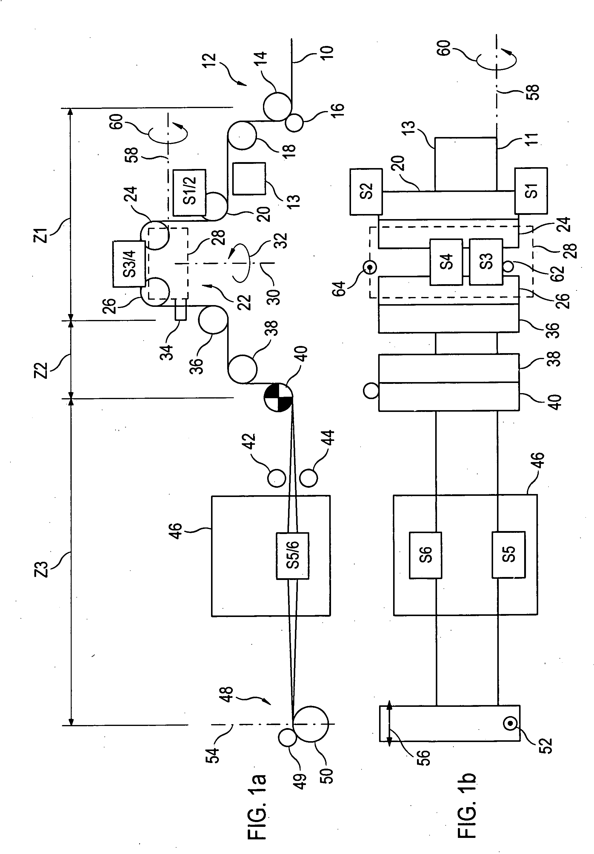
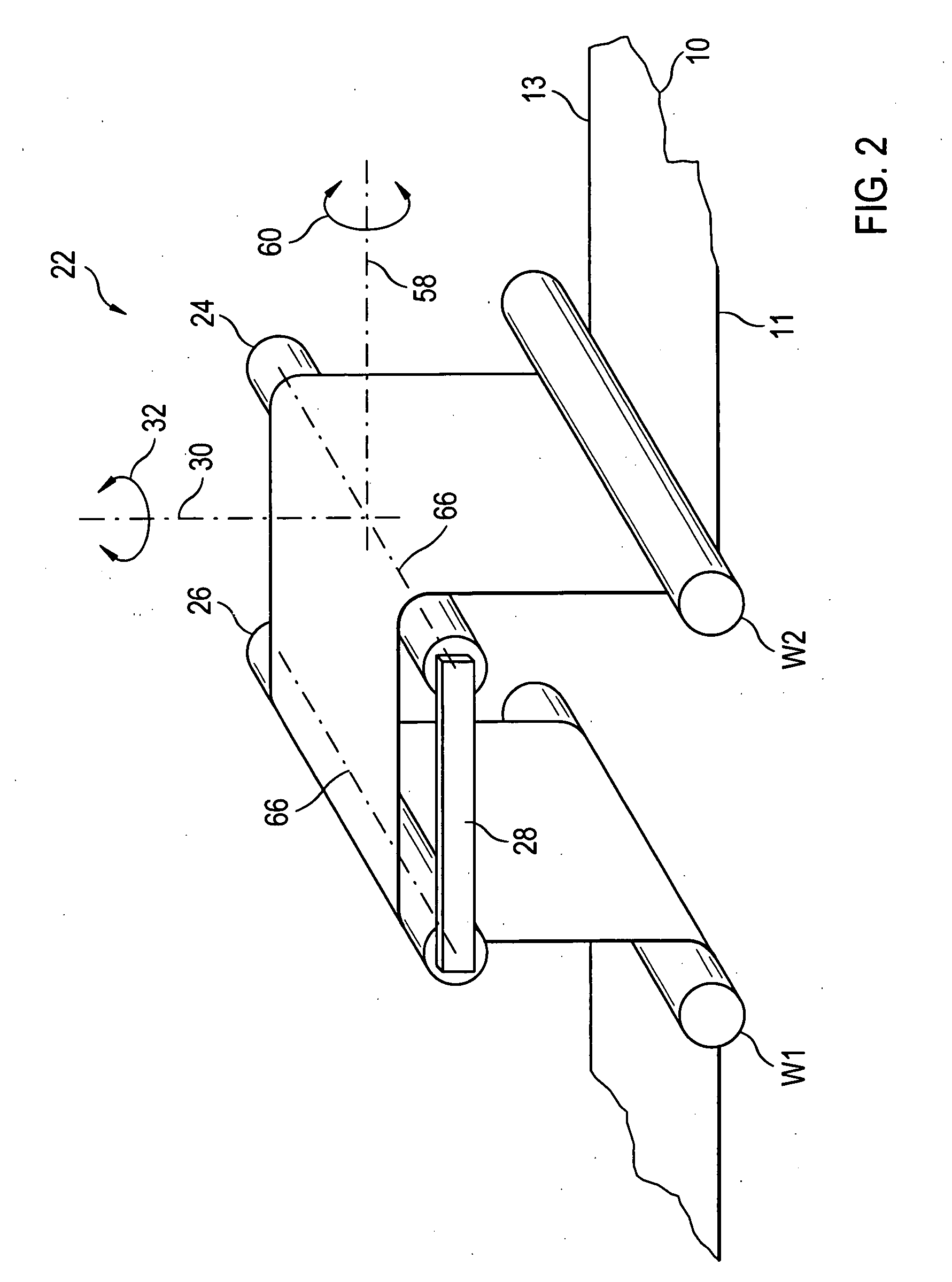
[0044]FIGS. 1a and 1b schematically show the transport of a continuous paper web 10 through a high-performance printer. FIG. 1a is a schematic side view, while FIG. 1b is a top view. The web transport through the printer takes place in three zones Z1, Z2 and Z3. In zone Z1, the paper web 10 is conveyed through a retracting device 12 comprising a roller 14 and a counter-pressure roller 16. The retracting device 12 serves to apply a predetermined web tension in a transport direction to the paper web 10. Subsequently, the paper web 10 is deflected at a deflection roller 18 and is supplied to a feed roller 20 which is located upstream a rotary frame 22 as viewed in the transport direction. The feed roller 20 comprises two sensors S1 and S2 for measuring the web tensile force as will be explained in more detail further below. The rotary frame 22 comprises two rollers 24 and 26, the axes of which are parallel and supported by a frame 28 illustrated in broken lines. The frame 28 is pivotab...


PUM


Abstract

A device and a method for controlling a position of a lateral edge of a continuous web of a recording medium in a printer or copier provides that sensors are provided. Signals of the sensors are supplied to a control device which includes an actuator. The actuator changes the position of the lateral edge of the web.

Description

BACKGROUND OF THE INVENTION [0001] 1. Field of the Invention [0002] The present invention relates generally to a device and a method for controlling the position of the lateral edge of a continuous web of a recording medium in a printer or copier. [0003] 2. Description of the Related Art [0004] In many printers or copiers, a continuous web such as a paper web is used as a recording medium, this web either being provided with a marginal perforation or not. If marginal perforations are provided, then the guidance of this web through the printer or copier is relatively easy since the lateral edge of the web is clearly defined by the engagement of pin-feed wheels in the marginal perforation. If the web has no marginal perforation, then a lateral displacement of the lateral edge can occur during the transport of the web through the copier or printer owing to inhomogeneities in the web, and the print image cannot be printed in a positionally accurate way. [0005] In order to achieve a posi...

Claims


Application Information

Patent Timeline
Patent Type & Authority Applications(United States)
IPC IPC(8): B65H23/02B65H23/038
CPCB65H23/0204B65H2404/14212B65H23/038
Inventor WINTER, HANSGASSNER, GUNTER
Owner OCE PRINTING SYST
Learn More