
Installation for sterilizing articles by electron bombardment

a technology of electron bombardment and installation, which is applied in the field of installation of sterilizing articles by electron bombardment, can solve the problems of deteriorating the portions of articles closest to the bombardment device, high-power electron bombardment running the risk of propagating outside the enclosure, and causing operators to move around the installation, so as to minimize the deterioration of an article

Inactive Publication Date: 2005-07-21
SERAC GROUP
View PDF29 Cites 80 Cited by
  • Summary
  • Abstract
  • Description
  • Claims
  • Application Information

AI Technical Summary

Benefits of technology

[0006] A main object of the invention is to provide an installation for sterilizing articles that enables the articles to be sterilized sufficiently both internally and externally by means of electron bombardment, and while minimizing deterioration of an article due to the electron bombardment.
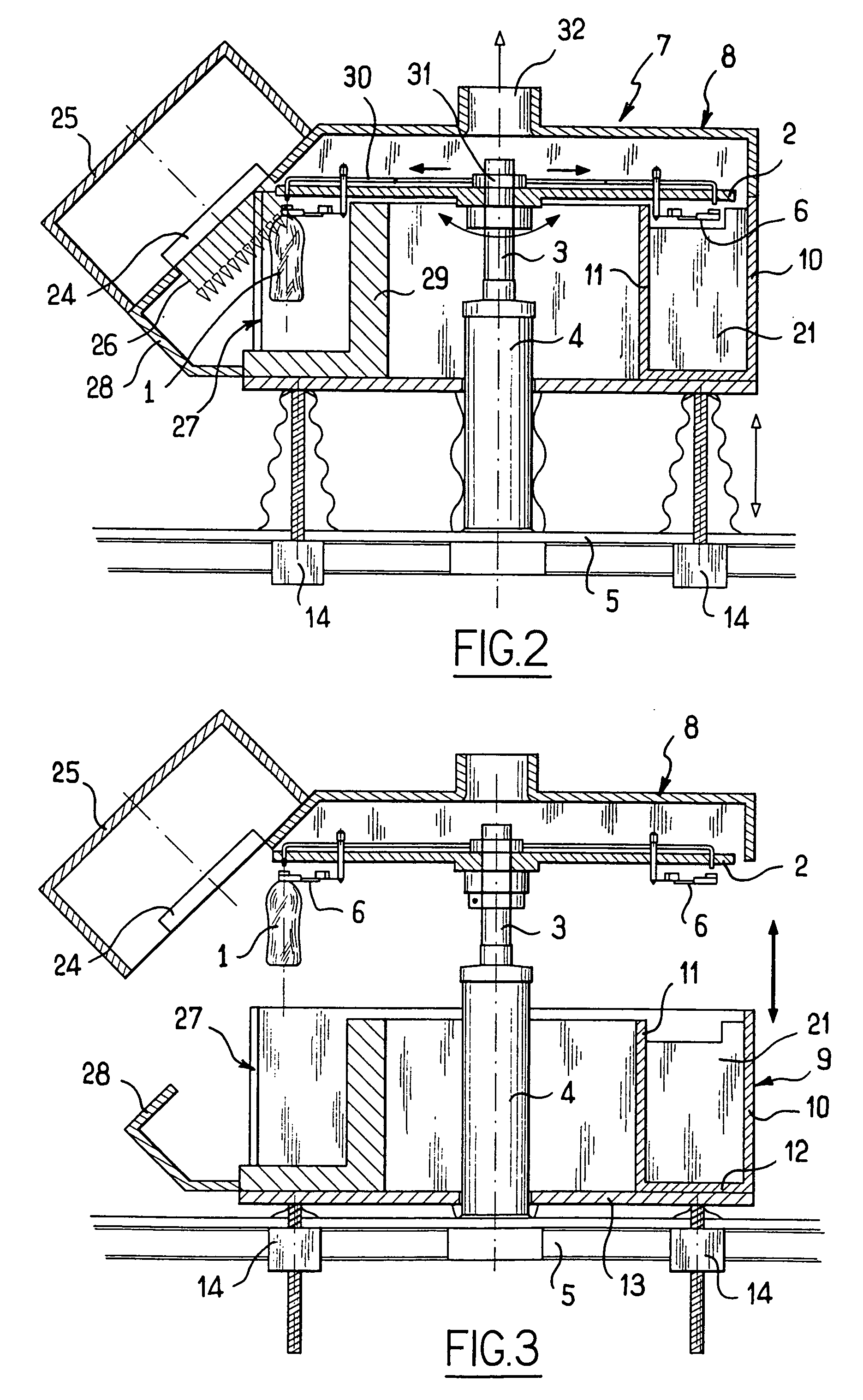
[0009] Thus, by appropriately positioning the electron bombardment members as a function of the shape of the article to be sterilized, it is possible to ensure that the electron bombardment member is facing a portion of the article that is of small thickness, thus making it possible to ensure that all portions of the article are sterilized, while using electron bombardment at low energy. This enables a complete sterilization of the article, including the bottom of a receptacle, without deterioration of the article.
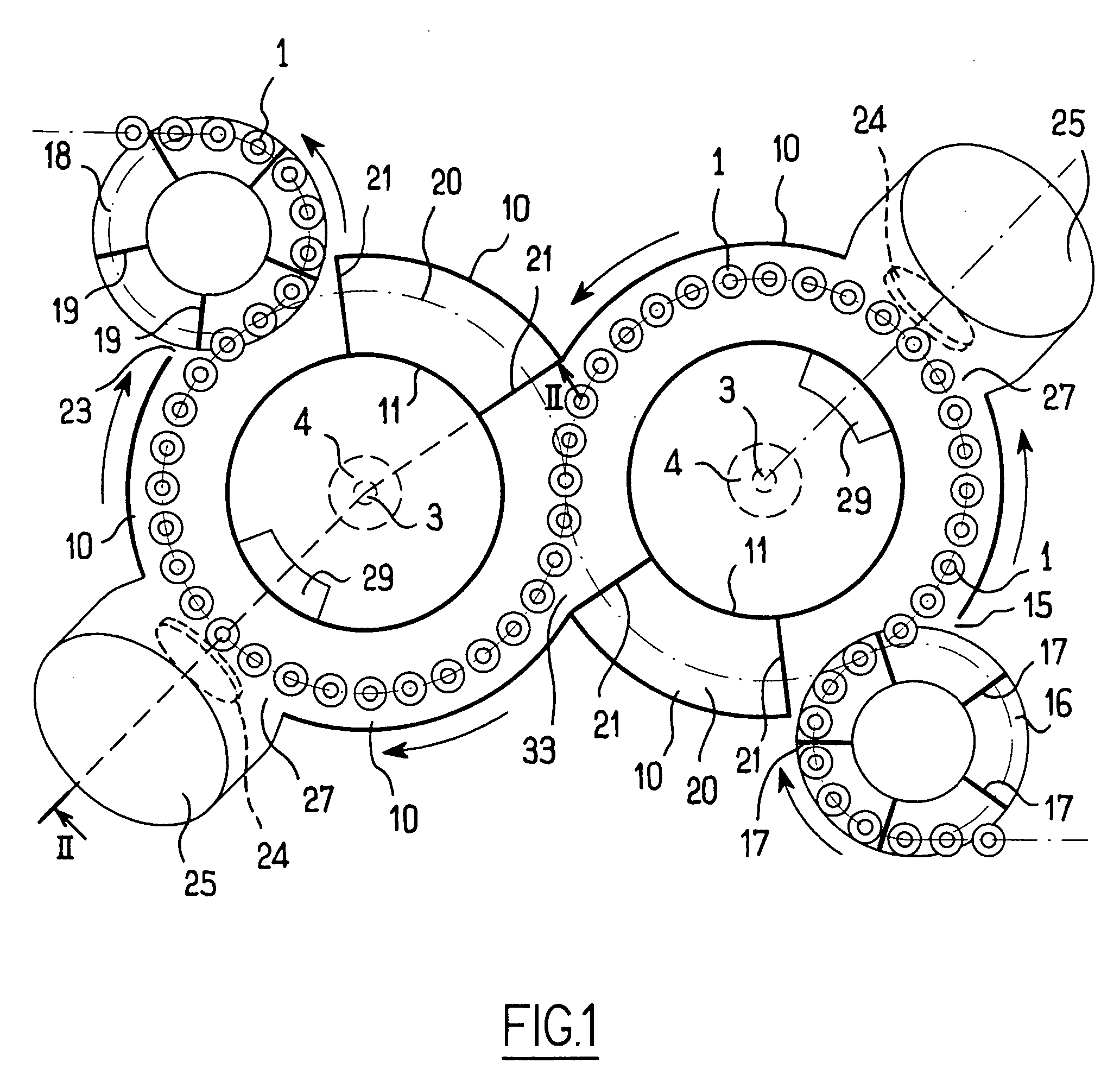
[0010] In another aspect of the invention, the support device comprises at least two support members disposed to support the receptacles in various positions corresponding to respective electron bombardment members, and preferably, the support members are rotary platforms disposed to cause the articles to follow an S-shaped path. This ensures that the support members do not form obstacles to propagation of the radiation while an article is passing in front of the corresponding electron bombardment member.
[0011] In yet another advantageous aspect of the invention, the enclosure has side walls presenting a curvilinear or zigzag profile. This ensures that the electron radiation is subjected to a large number of reflections on the walls of the enclosure before reaching the inlet opening or the outlet opening, such that the radiation escaping from the enclosure has residual energy that is low enough to constitute no danger for operators moving around the installation.
[0012] According to yet other advantageous aspects of the invention, the enclosure includes wall elements disposed to minimize the flow of air inside the enclosure, and the installation includes a device for injecting a sterile gas into the inside of the enclosure, preferably disposed vertically above the articles. This simultaneously minimizes the amount of polluted air that penetrates from outside the enclosure and the amount of electron radiation that is emitted outside from the enclosure.

Problems solved by technology

High-power electron bombardment then raises the problem of deteriorating the portions of the article that are closest to the bombardment device, in particular the neck when the article is a bottle.
In addition, high-power electron bombardment runs the risk of propagating outside the enclosure and thus of constituting a danger for operators moving around the installation.

Method used


Image

  • Installation for sterilizing articles by electron bombardment
  • Installation for sterilizing articles by electron bombardment
  • Installation for sterilizing articles by electron bombardment

Examples


Embodiment Construction

[0017] The invention is described below with reference to an installation for sterilizing bottles 1.

[0018] In the embodiment shown, the installation has two bottle-support members comprising in conventional manner a rotary platform 2 (not shown in FIG. 1) supported by a shaft 3 driven in rotation by a motor 4 carried by a frame 5. The rotary platform 2 includes, in likewise conventional manner, grips 6 suitable for taking hold of the bottles 1 around a portion of the neck of each bottle, while leaving the neck uncovered towards the outside of the platform.

[0019] The rotary platforms 2 are disposed adjacent to each other and are driven to rotate in opposite directions. The grips 6 are also controlled in conventional manner by a control member (not shown) enabling the bottles to be transferred from one rotary platform to the other as they pass through the point where the rotary platforms are tangential to each other, so that the bottles follow an S-shaped path, as shown in FIG. 1.

[...


PUM


Abstract

An installation for sterilizing articles comprises an enclosure having an inlet opening and an outlet opening, a support device for moving the articles inside the enclosure, and two electron bombardment members disposed on different orientations relative to the articles to be sterilized and inclined relative to the longitudinal axis of the articles.

Description

[0001] The present invention relates to an installation for sterilizing articles, and more particularly but not exclusively for sterilizing bottles. BACKGROUND OF THE INVENTION [0002] Installations for sterilizing articles, in particular trays for food products, are known, such an installation comprising an enclosure with a conveyor passing therethrough having the articles disposed thereon, and an electron bombardment device disposed above the conveyor for treating the articles with vertical radiation. Such installations are satisfactory for articles of small height, and they enable articles to be sterilized while using low-energy electron radiation. [0003] In contrast, when the articles are of considerable height and / or thickness, for example when the articles are bottles, it is necessary to increase the electron bombardment energy very considerably so that the electron radiation can reach the bottoms of the bottles after passing through their walls and still have enough energy to ...

Claims


Application Information

Patent Timeline
IPC IPC(8): A23L3/26A61L2/03A61L2/08B01J19/08
CPCA23L3/26A61L2202/23A61L2/087
Inventor DUMARGUE, GUYGRUSON, BERTRANDRAYNAUD, DELPHINE
Owner SERAC GROUP
Learn More