Linkage system

a linkage system and linkage technology, applied in the field of linkage systems, can solve the problems of insufficient rigidity of the link mechanism, the weight of the tool, or the load capacity of the traveling plate, and the entire mechanism and then the system itself becoming bulky, etc., to achieve good assemblability and production, high rigidity, and easy installation

Active Publication Date: 2005-07-21
NTN CORP
View PDF5 Cites 97 Cited by
  • Summary
  • Abstract
  • Description
  • Claims
  • Application Information

AI Technical Summary

Benefits of technology

[0015] Based on the foregoing, an object of the present invention is to provide a linkage system that offers high rigidity and good assemblability and producibility, and enables parts such as rotary transmission components and actuators to be readily installed.

Problems solved by technology

On the other hand, if the operating range of the traveling plate needs to be increased in the parallel link mechanism, the links have to be extended because each link has a relatively small operating angle range, and the entire mechanism and then the system itself become bulky.
Further, because of relatively low rigidity of the entire mechanism, the weight of the tool, or the load capacity of the traveling plate, has to be limited to a small range.
For example, the rigidity of the link mechanism is not satisfactorily high because of cantilevered structure at the revolute joints thereof.
The assemblability of the link mechanism is poor because the input-side and output-side link hubs, end links, and center links are coupled to each other with revolute joints.
Furthermore, because these parts each have a complex shape, they do not lend themselves to be readily produced.
Another problem was that there was little freedom of installation of the rotary transmission components and actuators because the space left in the link mechanism was small.
It was hard to install other necessary parts that were large, such as rotation angle sensing means for measuring rotational angles of the input-side end links.

Method used


Image

  • Linkage system
  • Linkage system
  • Linkage system

Examples


Embodiment Construction

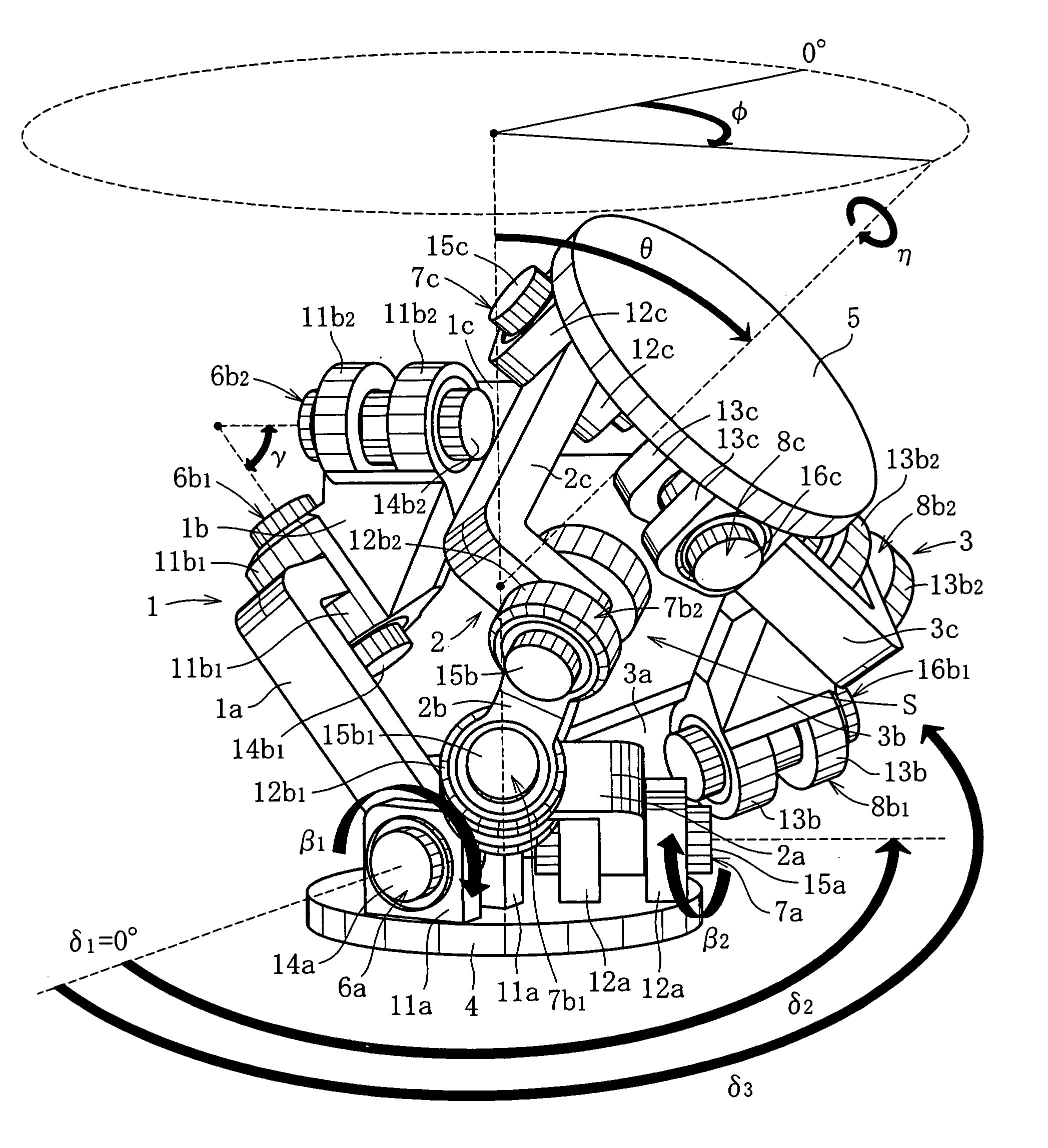
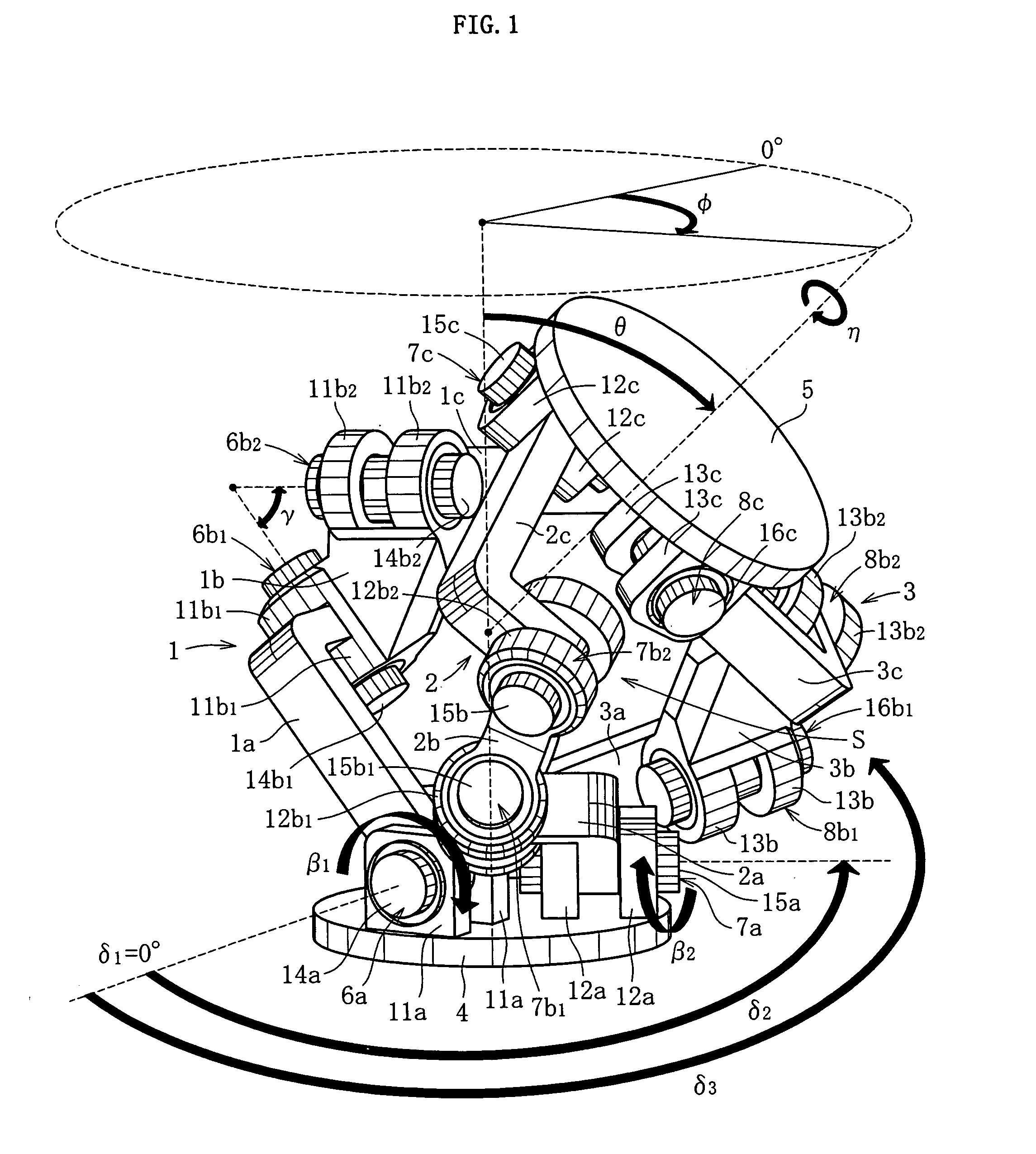
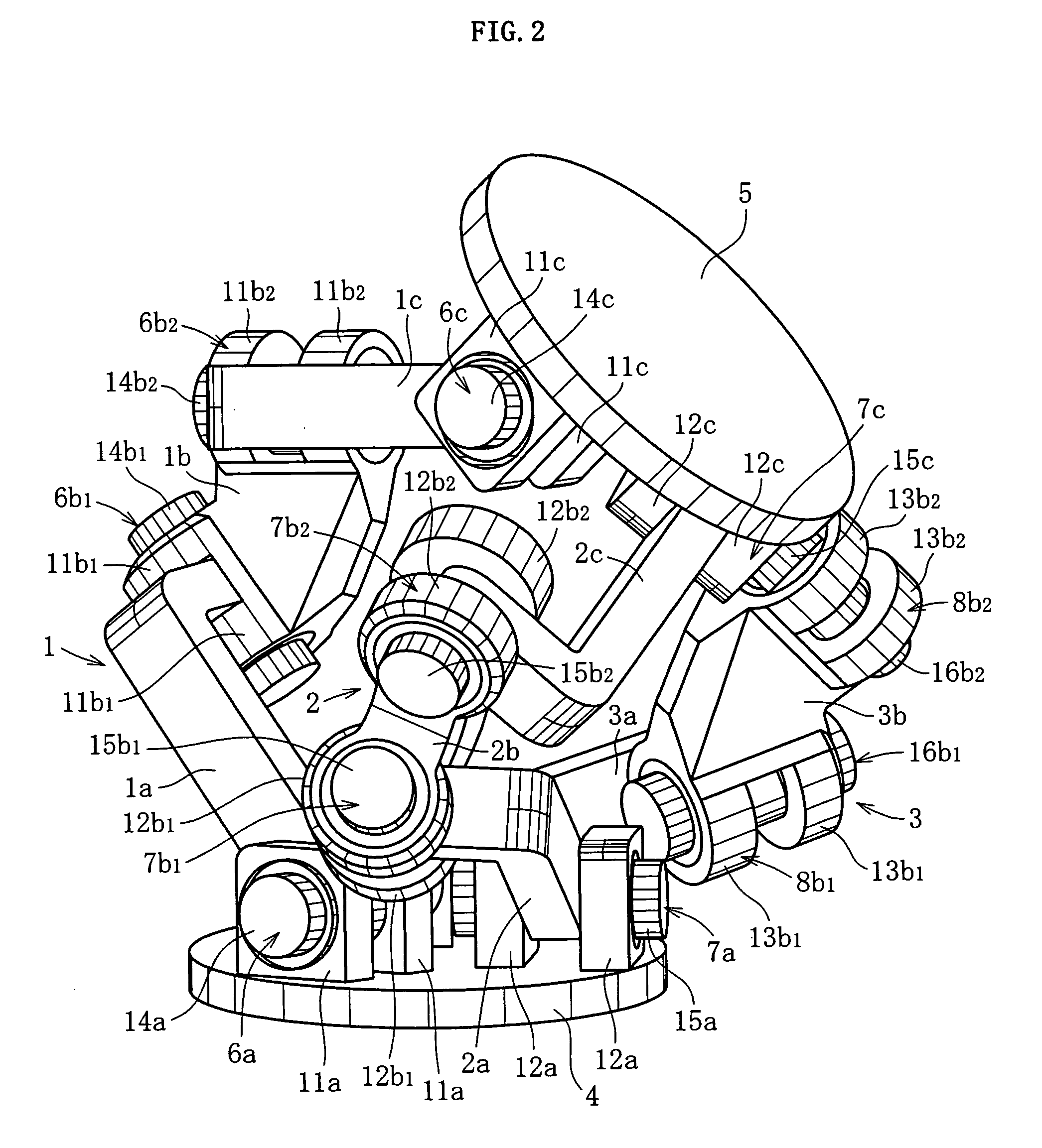
[0038]FIGS. 1 and 2 show linkage systems of the invention used, for example, for a joint of an articulated robot that performs complex processing or handling of goods in a three-dimensional space at high speed and with high precision. The system includes three sets of link mechanisms 1 to 3, which have a geometrically identical construction to one another. The basic structure of the link mechanisms 1 to 3 is as disclosed in the Japanese Patent Application No. 2003-40086 previously filed by the present applicant.

[0039] As shown in FIGS. 1 and 2, the link mechanism 1 (2, 3) forms a three-link chain, including an end link 1a (2a, 3a) provided on the input side and rotatably coupled to a disk-like input member 4, an end link 1c (2c, 3c) provided on the output side and rotatably coupled to a disk-like output member 5, a center link 1b (2b, 3b) rotatably coupled to both the end links 1a (2a, 3a) and 1c (2c, 3c) to connect both the end links, and four revolute joints 6a (7a, 8a), 6b1 (7b1...


PUM


Abstract

A linkage system which offers high rigidity and good assemblability and producibility, and enables parts such as rotary transmission components and actuators to be readily installed. A linkage system includes an input member disposed on an input side, an output member disposed on an output side, and three or more link mechanisms, each link mechanism consisting of end links rotatably coupled to the input member and the output member, respectively, a center link rotatably coupled to the end links on the input side and the output side, and four revolute joints by which the end links are rotatably coupled to the input and output members, and to the center link. The link mechanism being geometrically identical with respect to a center cross-sectional plane relative on the input and output sides. Each of the revolute joints of the link mechanism includes bearings that support at both ends of the revolute joint.

Description

BACKGROUND OF THE INVENTION [0001] 1. Field of the Invention [0002] The present invention relates to a linkage system used, for example, for a joint of an articulated robot that performs complex processing or handling of goods in a three-dimensional space at high speed and with high precision. [0003] 2. Description of the Related Art [0004] For example, Japanese Patent Laid-Open Publication No. 2000-94245 discloses a linkage system with a parallel link mechanism that performs complex processing or handling of goods in a three-dimensional space at high speed and with high precision. [0005] The parallel link mechanism adopted in such a linkage system includes a plurality of links that connect a base plate and a traveling plate and cooperatively extend and retract to change the position and orientation of the traveling plate relative to the base plate. Tool is attached to the traveling plate of the parallel link mechanism, while a workpiece is held on a table which is designed rotatabl...

Claims


Application Information

Patent Timeline
Patent Type & Authority Applications(United States)
IPC IPC(8): B25J17/02B25J17/00F16H21/54
CPCB25J17/0266Y10T74/20335Y10T74/20329B25J9/0048
Inventor ISOBE, HIROSHISONE, KEISUKEISHIKAWA, TOMOMI
Owner NTN CORP
Why Eureka
Try Eureka