Wood golf club head

a golf club head and wood technology, applied in the field of golf clubs, to achieve the effect of reducing weight, reducing weight, and increasing siz

Inactive Publication Date: 2005-07-21
CHUANG CHENG YU
View PDF10 Cites 72 Cited by
  • Summary
  • Abstract
  • Description
  • Claims
  • Application Information

AI Technical Summary

Benefits of technology

[0009] In addition, the head housing is provided with two gaps respectively at the heel and the toe. The gaps are extended from tops of the heel and the toe to where adjacent to the sole, or to the sole. The arms of the crown shield the gaps respectively. With such structure, the golf club head is lighter such that the head can be made into a greater size or can be mounted with more weight devices at the sole to adjust

Problems solved by technology

The only problem of the composite material crown is that how t

Method used


Image

  • Wood golf club head
  • Wood golf club head
  • Wood golf club head

Examples


Embodiment Construction

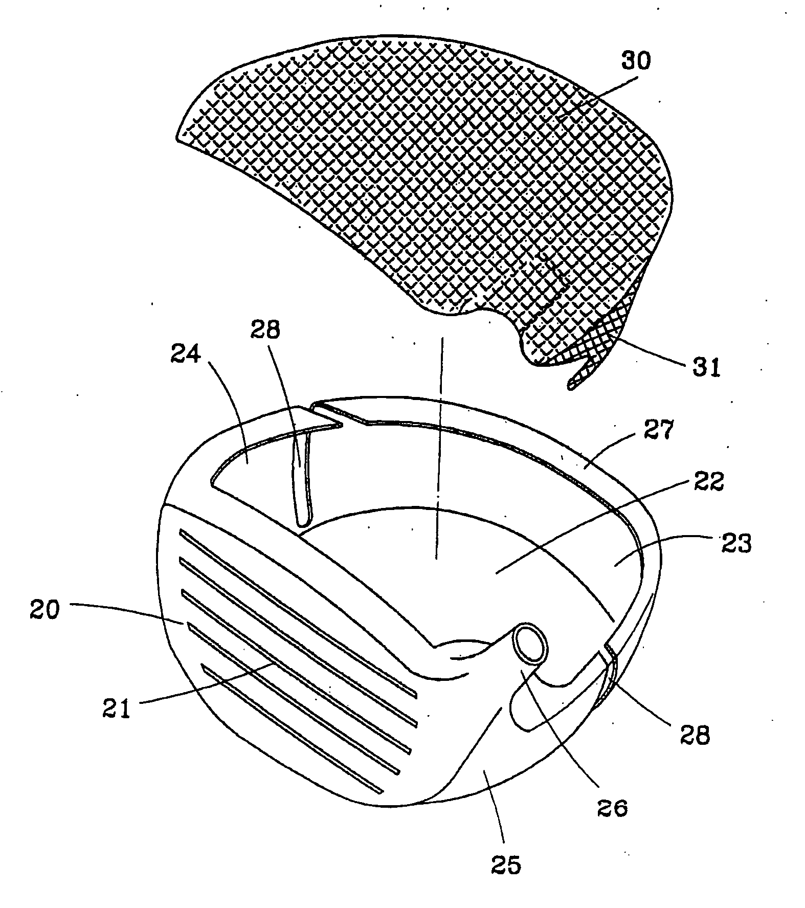
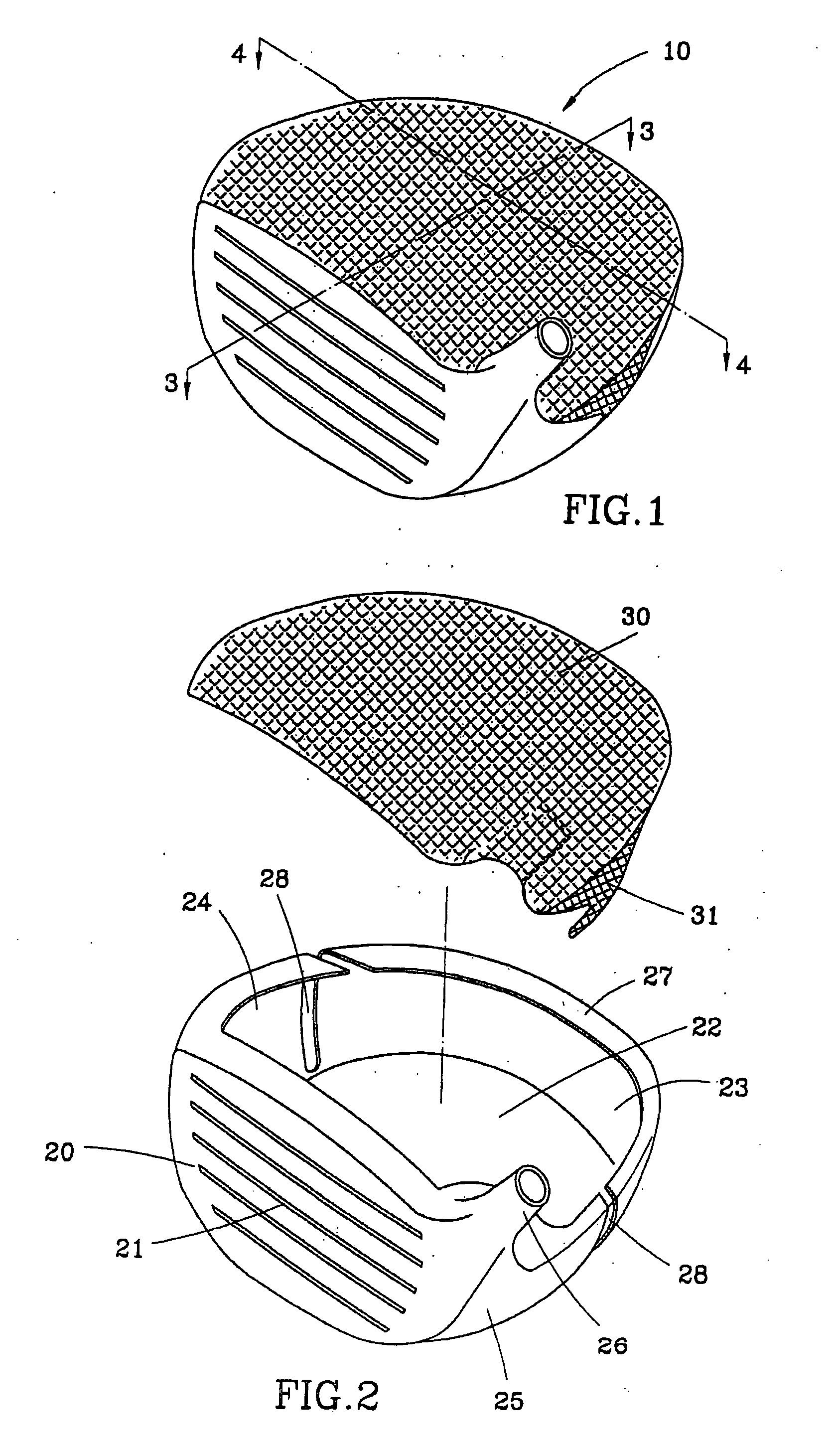
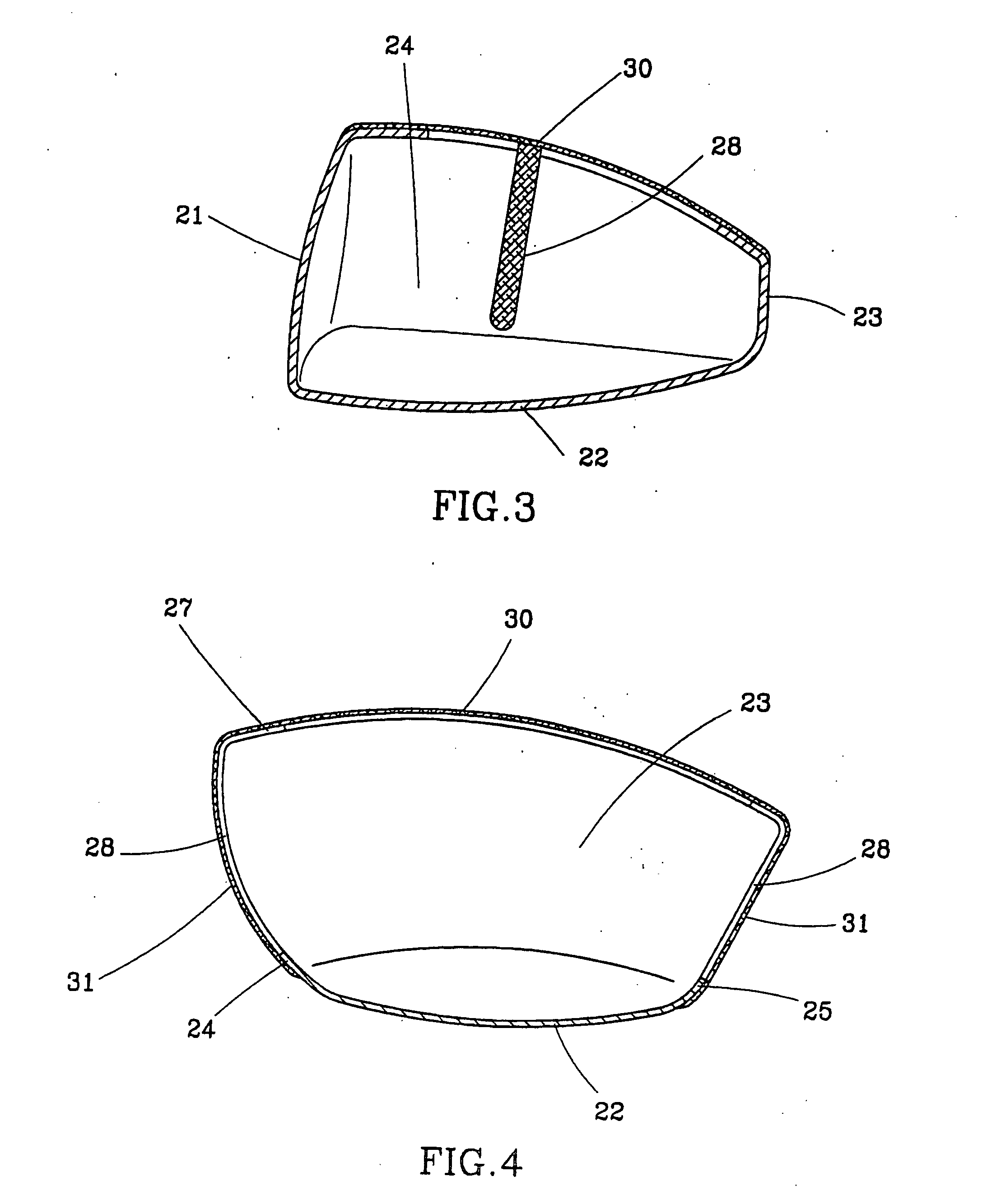
[0014] As shown in FIGS. from FIG. 3 to FIG. 5, a golf club head 10 of the first preferred embodiment of the present invention comprises:

[0015] A metallic head housing 20 has a face 21, a sole 22, a rear 23, a toe 24, a heel 25, and a neck 26. The head housing 20 is hollow and has an opening at a top thereof. Around the top of the head housing 20 is an annular shoulder portion 27 and at the toe 24 and the heel 24 is a gap 28 respectively. The gaps 28 are extended downwardly from the shoulder portion 27 to the toe 24 and the heel 24 at where adjacent to the sloe 22 respectively.

[0016] A nonmetallic crown 30, which is made of carbon fiber prepreg epoxy resin, or other fiber reinforced resin or plastics in the present preferred embodiment, has two arms 31 at opposite sides thereof. The crown is a thin plate to be coupled to the top of the head housing 20, in which the shoulder portion 27 is attached to a bottom of the crown 30 and the arms 31 of the crown 30 are attached on the toe 2...


PUM


Abstract

A golf club head is mainly consisted of a metallic head housing having and a nonmetallic crown. The metallic head housing, which hollow and is open at a top thereof, has a face, a sole, a rear, a toe and a heel. At the toe and the heel of the head housing is a gap respectively. The crown coupled to the top of the head housing, wherein the crown has two arms coupled to the toe and the heel of the head housing respectively to shield the gaps.

Description

BACKGROUND OF THE INVENTION [0001] 1. Field of the Invention [0002] The present invention relates generally to a golf club, and more particularly to a wood golf club head. [0003] 2. Description of the Related Art [0004] A conventional wood golf club head has a hollow housing which a center of gravity is positioned at bottom and rear as possible. In such point, a crown, which is a top potion of the housing, is made as thinner as possible. The conventional crown is made of a metal, which is too heavy to make the center of gravity of the golf club head at bottom and rear. In the present days, there is a crown made of composite material, which the composite material is lighter in weight, so that the center of gravity of the golf club head is positioned lower. [0005] The only problem of the composite material crown is that how to couple the crown to the metallic housing in a firm condition. SUMMARY OF THE INVENTION [0006] The primary objective of the present invention is to provide a gol...

Claims


Application Information

Patent Timeline
IPC IPC(8): A63B53/04A63B59/00
CPCA63B53/0466A63B2053/0437A63B2209/023A63B59/0092A63B60/54A63B53/0437
Inventor CHUANG, CHENG-YU
Owner CHUANG CHENG YU
Why Eureka
Try Eureka