Optical probe accessory device for use in in vivo diagnostic procedures

an optical probe and accessory device technology, applied in the direction of spectroscopy, catheters, instruments, etc., can solve the problems of affecting the development of optical probes for clinical use, affecting and affecting the patient's comfort, so as to maximize patient comfort, optimize light transmission, and avoid sacrificing the quality of optical data obtained

Inactive Publication Date: 2005-07-21
MEDISPECTRA
View PDF99 Cites 70 Cited by
  • Summary
  • Abstract
  • Description
  • Claims
  • Application Information

AI Technical Summary

Benefits of technology

[0006] The invention recognizes that optical probes function both as medical access devices and as instruments which collect complex optical data. The invention provides an optical probe accessory device which accesses luminal spaces within the body of a patient without sacrificing the quality of optical data obtained. The accessory device further comprises either, singly, or in combination, selectable features which optimize light transmission, maximize patient comfort, and provide single-use capabilities.
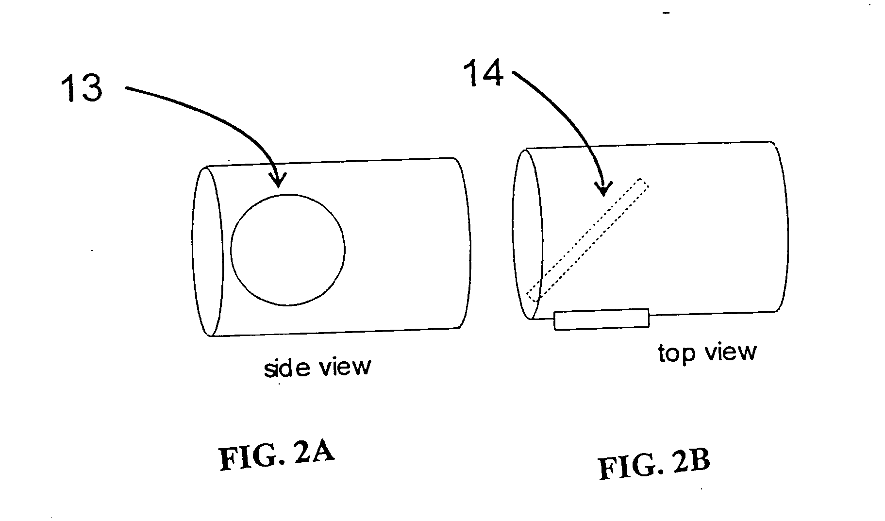
[0007] In one aspect of the invention, an accessory device for an optical probe is provided which creates an optimal light path between the optical probe and a target tissue. Optional optical elements are provided which enhance the light transmitting and light receiving functions of the probe. In one embodiment, an accessory device comprises optical elements which create an optical waveguide to improve optical data collection by the probe. In this embodiment, the accessory device includes a window which functions as an objective for the optical probe's illumination elements. In other embodiments of the invention, the window is coated with anti-fog and / or anti-glare agents to maximize the passage of diagnostic light to and from the probe. In still other embodiments, the accessory device is adapted to function with an optical probe which comprises a plurality of optical fibers and the accessory device comprises a plurality of openings sized to accept a plurality of light transmitting fibers from the optical probe.
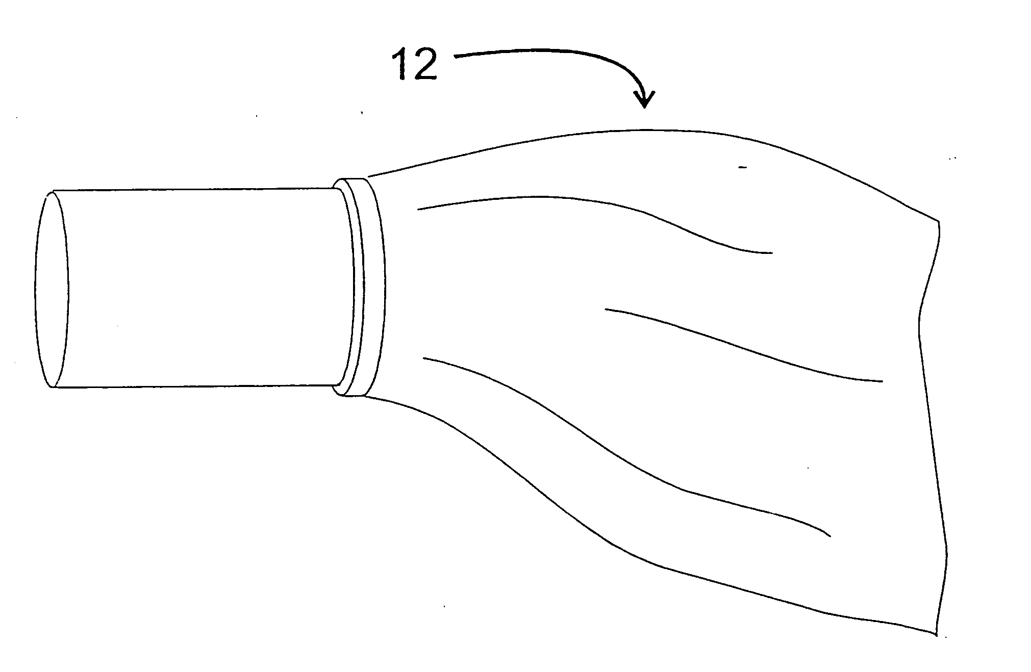
[0009] For example, an optical probe accessory device which comprises, at least in portion, a flexible material which conforms to the shape of a body space being accessed is contemplated by the present invention. The flexible portion provides a shield between the tissue being assayed by the optical probe and the probe itself. In another embodiment, a segment of the flexible portion conforms to an end of the optical probe bearing illumination optics, protecting the illumination optics of the probe from bodily fluids while shielding the patient from contaminants. In still another embodiment, the flexible nature of the accessory device allows it to be rolled up before and after use with the probe.
[0014] The instructions transmitted by the processor control the actuation of the optical probe. For example, in one embodiment, the system includes a light source in communication with both the processor and the optical probe. Transmission of light from the light source to the probe relies upon instructions received from the processor. In another embodiment, instructions from the processor can include particular operating parameters relating to a tissue-specific diagnostic procedure (for example, but not limited to the diagnosis of cervical cancer). Use of an accessory device with an electrical element which identifies the device as one which is suited for accessing the cervix triggers the processor to implement operating parameters suited to the diagnosis of cervical cancer. Thus, the system provides flexibility that allows the optical probe to be used with a variety of accessory devices in a variety of diagnostic procedures.

Problems solved by technology

However, the development of optical probes for clinical use has been hampered due to the difficulty of miniaturizing the optical elements necessary for the collection of optical data.
Additional constraints arise because an optical probe, like any medical access device, must be decontaminated and sterilized prior to reuse.
The delicate construction of light directing and focussing elements within the optical probe generally make it difficult, if not impossible, to sterilize the probe.

Method used


Image

  • Optical probe accessory device for use in in vivo diagnostic procedures
  • Optical probe accessory device for use in in vivo diagnostic procedures
  • Optical probe accessory device for use in in vivo diagnostic procedures

Examples


Embodiment Construction

[0024] Because an accessory device according to the invention complements the function of an optical probe such accessory devices provide more than merely a sheath for an optical probe. An accessory device of the invention comprises a number of optional features which a user can select in optimizing the accessory device to suit a particular application. Any or all of these options can be present in an accessory device according to the invention. Because of the many permutations of accessory devices which can be designed according to the invention, the optical probe itself acquires more versatility and can be used in a variety of diagnostic settings. It will be apparent to those of skill in the art after reading this disclosure that other options can additionally be provided, and such options are encompassed within the scope of the invention. All that is required to practice the present invention, is that the accessory device permit optical data collection by an optical probe without...


PUM

PropertyMeasurementUnit
thicknessaaaaaaaaaa
thicknessaaaaaaaaaa
half angleaaaaaaaaaa

Abstract

The present invention recognizes that optical probes function both as medical access devices and as instruments which collect complex optical data. The invention provides an optical probe accessory device which can access luminal spaces within the body of a patient without sacrificing the quality of optical data obtained. The accessory device further comprises either, singly, or in combination, selectable features or options which optimize light transmission, maximize patient comfort, and provide single-use capabilities.

Description

RELATED APPLICATIONS [0001] The application claims priority to U.S. Provisional Application Ser. No. 60 / 138,235, filed on Jun. 9, 1999 and is also a continuation-in part of U.S. patent application Ser. No. 09 / 481,762, filed Jan. 11, 2000, which claims priority to U.S. Provisional Application Ser. No. 60 / 115,373, filed Jan. 11, 1999, and is a continuation-in-part of U.S. patent application Ser. No. 09 / 241,806, filed Feb. 2, 1999, which is a continuation-in-part of U.S. patent application Ser. No. 08 / 782,936, filed Jan. 13, 1997. The entirety of these applications is incorporated by reference.FIELD OF THE INVENTION [0002] The invention relates to an accessory device for an optical probe for use in in vivo diagnostic procedures. The accessory device provides an optimal optical path for light from an optical probe while minimizing patient discomfort. The accessory device features optional selectable elements to enhance its versatility in in vivo diagnostic procedures. BACKGROUND OF THE ...

Claims


Application Information

Patent Timeline
Patent Type & Authority Applications(United States)
IPC IPC(8): A61B1/00A61B5/00A61B19/00G01N21/47
CPCA61B1/00059A61B1/00062A61B1/00082A61B1/00096A61B1/00103A61B1/00135G01N21/4795A61B1/043A61B5/0071A61B5/0075A61B5/0084A61B2019/4873A61B2562/08A61B1/00142A61B2090/0814
Inventor NORDSTROM, ROBERTBEE, DAVIDMODELL, MARKHED, ZE'EVKWO, JENNIEEMANS, MATTHEW
Owner MEDISPECTRA
Why Eureka
Try Eureka