Balloon control apparatus

a control device and balloon technology, applied in the field of balloon control devices, can solve the problems of consuming a great deal of time and labor, affecting the maintenance work of the balloon control device, and affecting the operation

Inactive Publication Date: 2005-07-21
SRJ +1
View PDF3 Cites 85 Cited by
  • Summary
  • Abstract
  • Description
  • Claims
  • Application Information

AI Technical Summary

Benefits of technology

[0017] Therefore, according to the balloon control device of the present invention, it is possible to prevent l

Problems solved by technology

However, the conventional balloon control device has a possibility that an unclean matter such as body fluid is sucked into the device through the tube when the balloon is broken or when the connection of the tube is bad.
In such case, an electromagnetic

Method used


Image

  • Balloon control apparatus
  • Balloon control apparatus
  • Balloon control apparatus

Examples


Embodiment Construction

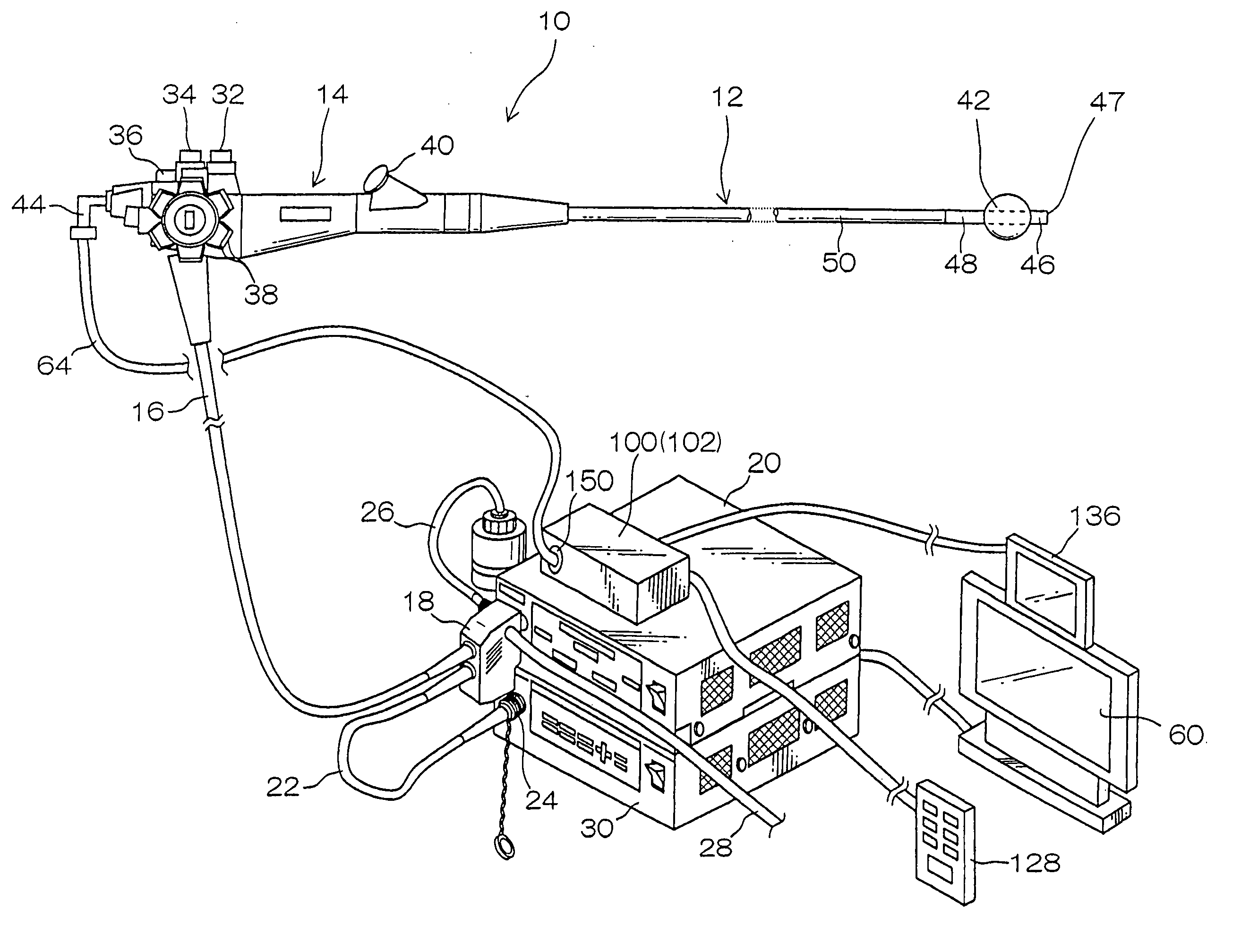
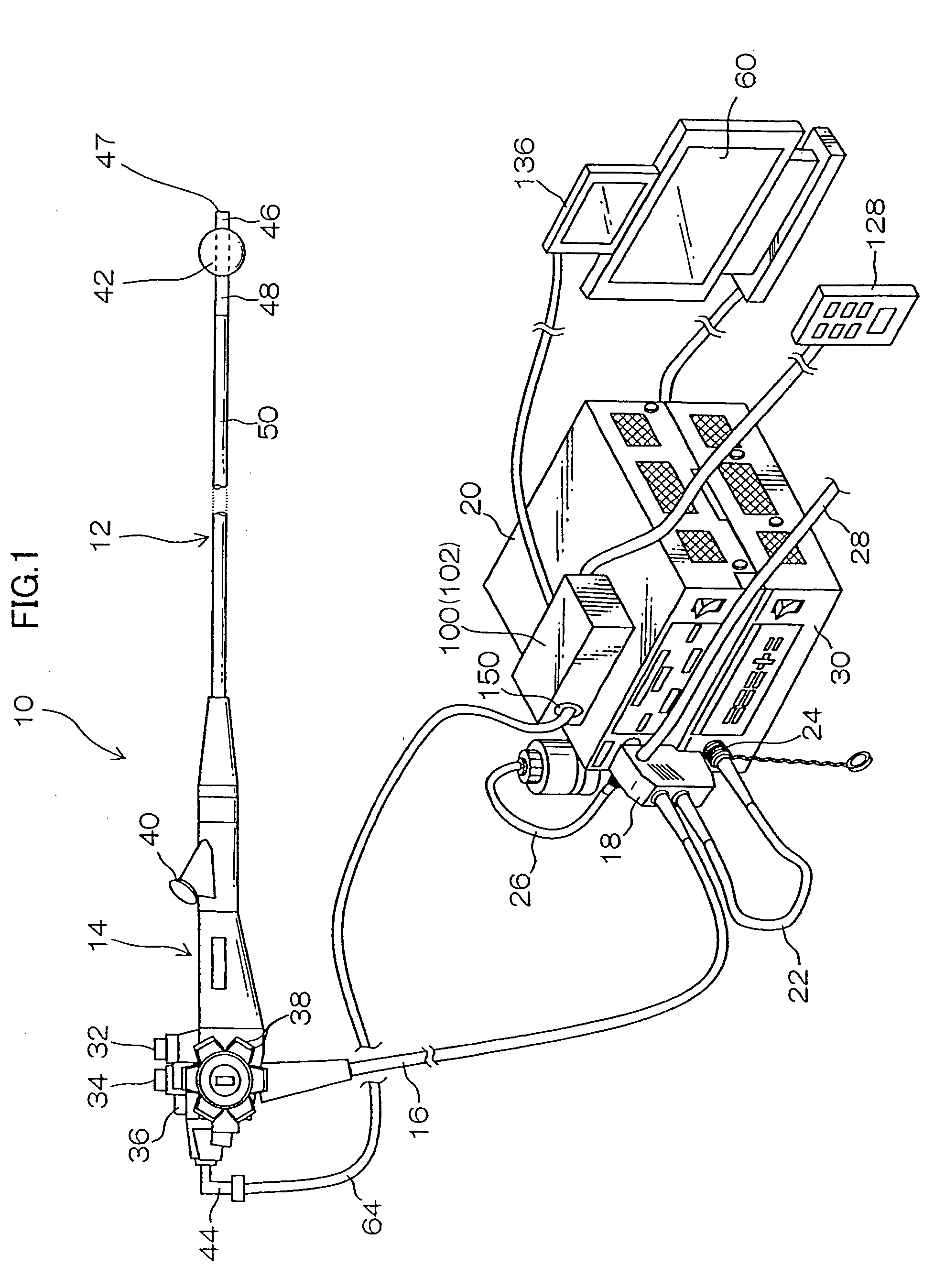
[0032]FIG. 1 is a schematic perspective view of an endoscope system according to an embodiment of the present invention. As shown in FIG. 1, the endoscope system is mainly comprised an endoscope 10, a light equipment 20, a processor 30, and a balloon control device 100.

[0033] The endoscope 10 is composed of an insertion unit 12 to be inserted into a body cavity, and a handy control unit 14 linked to the insertion unit 12. The insertion unit 12 and the handy control unit 14 are connected by a universal cable 16. While an LG connector 18 is provided at the tip of the universal cable 16, the LG connector 18 is connected to the light equipment 20. While an electrical connector 24 is connected to the LG connector 18 via a cable 22, the electrical connector 24 is linked to the processor 30. A gas feed / water feed tube 26 for supplying air or water, and a suction tube 28 for sucking air and body fluid are connected to the LG connector 18.

[0034] The handy control unit 14 is equipped with a...


PUM


Abstract

A balloon control device for controlling an expansion and contraction of a balloon fixed to one of an insertion unit of endoscope and an insertion adapter by supplying and suctioning of fluid to the balloon, comprising: a channel for conveying the fluid between the balloon control device and the balloon; and a gas/liquid separator for separating gas and liquid from the fluid in the channel.

Description

BACKGROUND OF THE INVENTION [0001] 1. Field of the Invention [0002] The present invention relates to a balloon control device, and more particularly to a balloon control device for controlling a balloon installed to an insertion unit of endoscope and an insertion adapter. [0003] 2. Description of the Related Art [0004] As disclosed in Japanese Patent Application Publication No. 2003-144378, an endoscope system using balloon is developed recently. In this case, the balloon is attached around the tip of an insertion unit of endoscope, or the tip of an insertion adapter in which covers on the insertion unit. Therefore, the insertion unit or the insertion adapter is fixed within the body cavity by expanding the balloon within the body cavity. [0005] The insertion unit and the insertion adapter are provided an air supply intake port communicating with the balloon at the base end of those. The air supply intake port is connected to a balloon control device by a tube. Air is supplied and s...

Claims


Application Information

Patent Timeline
IPC IPC(8): A61B1/01A61B1/00A61B1/05A61B1/12A61F2/958A61M16/04
CPCA61B1/00082A61B1/00154A61B1/018A61B1/12A61M16/0434A61M16/044A61M25/1018A61B1/05A61M25/10185A61M25/10188
Inventor SEKIGUCHI, TADASHIFUJIKURA, TETSUYANORINOBU, TOMOYA
Owner SRJ
Why Eureka
Try Eureka