Tapered bone fusion cages or blocks, implantation means and method

a technology of fusion cages or blocks and tapered bones, applied in the field of spine fusion, can solve the problem that the disc space may be too large for the pair of implants, and achieve the effect of great precision

Inactive Publication Date: 2005-07-21
RAY CHARLES D
View PDF18 Cites 68 Cited by
  • Summary
  • Abstract
  • Description
  • Claims
  • Application Information

AI Technical Summary

Problems solved by technology

The greatest problems associated with the instrumentation used for the implantation of these materials or devices to be implanted have been: (1) rigidly attaching a guiding assembly (usually tubular) onto or within the disc space of adjacent vertebrae for subsequent preparation of the bed and subsequent insertion of the appropriately tapered devices or cages while maintaining the proper spacing (for a plurality of implants) and angulation of the devices to be used, (2) reaming (tapered drilling) the recipient bed while rigidly maintaining the direction and depth of this process, creating the appropriate recipient bed, (3) tapping the recipient bed, or utilizing self-tapping cages, while maintaining the same initial angulation and spacing used in the above earlier stages, and (4) appropriate tightening of the circumferential fibers of the annulus with stabilization of the operated segment through a means to expand the disc.
Further, because the overall width of the two adjacent implants is twice their diameters, the pair of implants may be excessively wide for that disc space.

Method used


Image

  • Tapered bone fusion cages or blocks, implantation means and method
  • Tapered bone fusion cages or blocks, implantation means and method
  • Tapered bone fusion cages or blocks, implantation means and method

Examples


Embodiment Construction

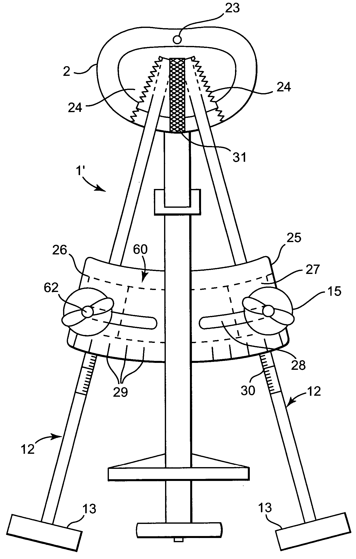
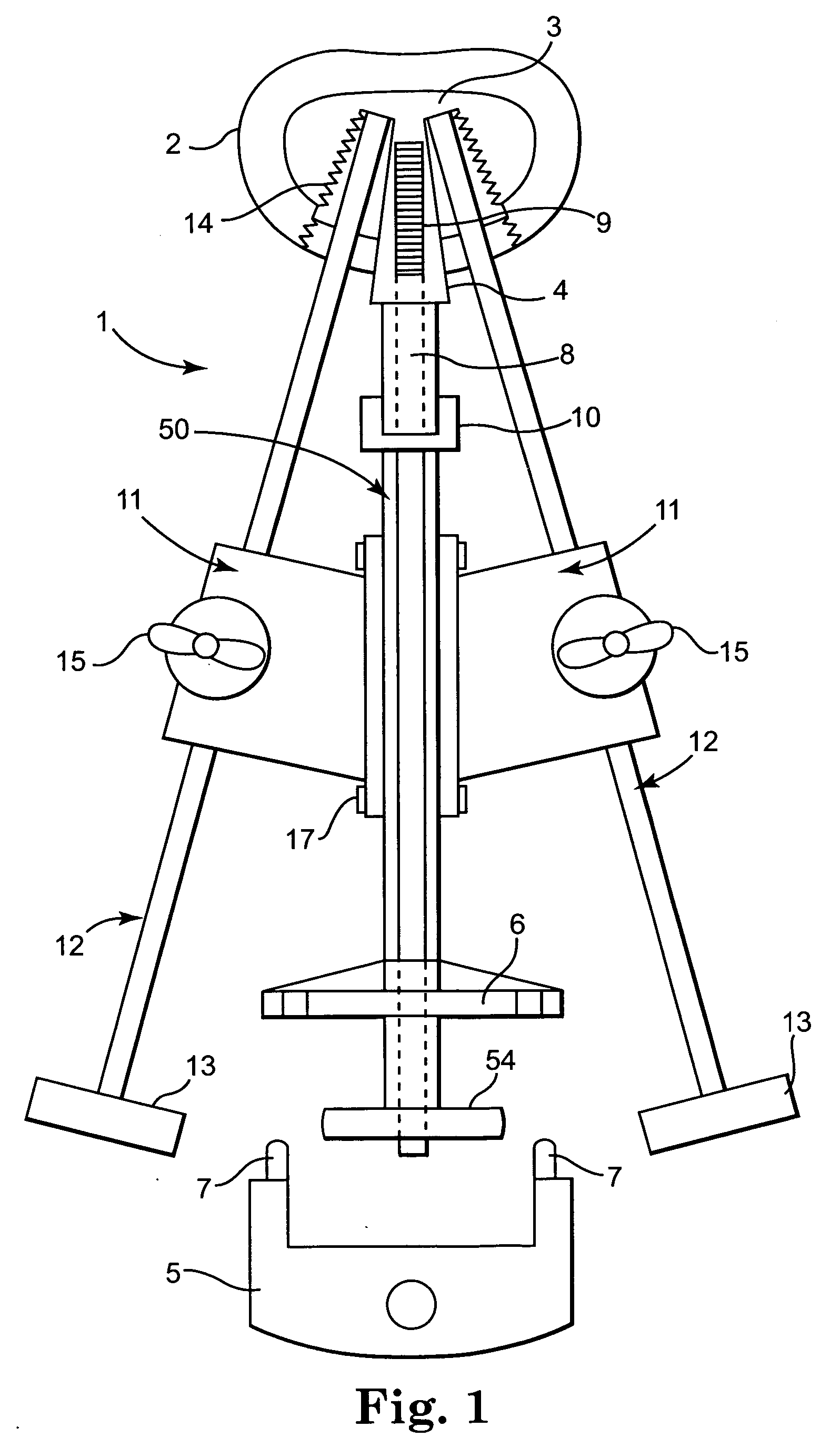
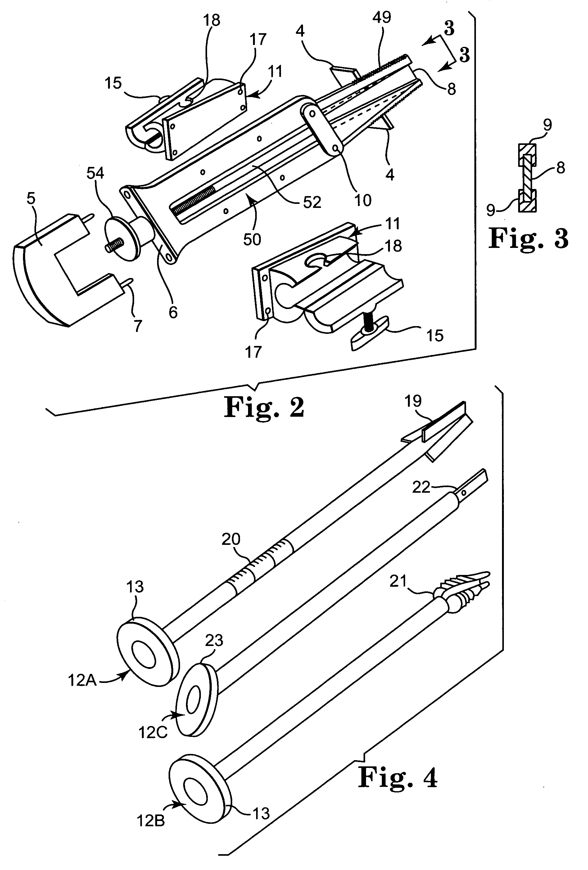
[0014] In the following Detailed Description, reference is made to the accompanying drawings, which form a part hereof, and in which is shown by way of illustration specific embodiments in which the invention may be practiced. In this regard, directional terminology, such as “top,”“bottom,”“front,”“back,”“leading,”“trailing,” etc., is used with reference to the orientation of the Figure(s) being described. Because components of embodiments of the present invention can be positioned in a number of different orientations, the directional terminology is used for purposes of illustration and is in no way limiting. It is to be understood that other embodiments may be utilized and structural or logical changes may be made without departing from the scope of the present invention. The following detailed description, therefore, is not to be taken in a limiting sense, and the scope of the present invention is defined by the appended claims.

[0015]FIG. 1 is a composite, diagrammatic plan view...


PUM


Abstract

A novel device and method for fusions inside a forward widely tapering human disc space. A stabilizing / guiding system is driven into and against the disc space. The device is further stabilized by spreading and gripping means inside both vertebral end plates. Rod retaining members hold calibrated rod units whose adapted tips perform reaming and threading of the disc space. Subsequently, the tapered cage or implant can be inserted by a free-hand method under direct vision into the prepared and tapered bed. Rod unit divergent angulation is preferably set to match that of the disc space as well as the implants so they obtain optimal distributed purchase of vertebral bone. In one embodiment, inserts are confluent with parallel medial walls rather than their long axes, increasing torsional or lateral translational stability and simplifying placement of additional bone chips. No tubular guide means are required.

Description

CROSS-REFERENCE TO RELATED APPLICATIONS [0001] This application claims the benefit of U.S. Provisional Patent Application Ser. No. 60 / 533,622, filed Dec. 31, 2003 and entitled “Tapered Bone; Fusion Cages or Blocks, Implantation Means and Method”, the teachings of which are incorporated herein in its entirety.BACKGROUND [0002] The present invention relates to fusions of the spine, more specifically to intradiscal or interbody fusions utilizing hollow, formed, perforated, threaded cages in severe, disabling discogenic back pain problems, with or without a herniation (protrusion) of the disc. [0003] Degenerative changes of the human spinal column often are accompanied by severe, disabling back pain; one method of success in eliminating such pain originating from within the disc, called discogenic pain, is to surgically eliminate the disc and create a fusion or bony union between adjacent vertebrae, eliminating the offending, painful disc. Several successful surgical devices and methods...

Claims


Application Information

Patent Timeline
Patent Type & Authority Applications(United States)
IPC IPC(8): A61B17/17A61B17/88A61F2/46
CPCA61B17/1757A61B2017/0256A61F2/4611A61F2002/4687A61F2002/448A61F2250/0006A61F2002/30538
Inventor RAY, CHARLES D.
Owner RAY CHARLES D
Why Eureka
Try Eureka