
Method of communications between MIMO stations

Inactive Publication Date: 2005-07-21
SAMSUNG ELECTRONICS CO LTD
View PDF24 Cites 46 Cited by
  • Summary
  • Abstract
  • Description
  • Claims
  • Application Information

AI Technical Summary

Benefits of technology

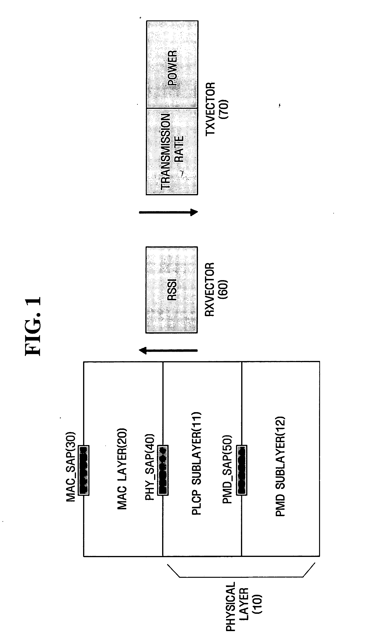
[0027] In the present invention, MIMO communications can be realized by using conventional spatial multiplexing MIMO chipsets, a detailed description of which, however, will not be presented here. For example, MIMO communications can be realized using an AGN 100 Wi-Fi chip set manufactured by Airgo Networks. The AGN 100 Wi-

Problems solved by technology

The conventional link adaptation methods described above are inappropriate for MIMO systems using a multi-antenna structure even though they are still effective for SISO systems using a single antenna structure.

Method used


Image

  • Method of communications between MIMO stations
  • Method of communications between MIMO stations
  • Method of communications between MIMO stations

Examples


Embodiment Construction

[0040] The present invention will now be described more fully with reference to the accompanying drawings, in which preferred embodiments of the invention are shown. This invention may, however, be embodied in many different forms and should not be construed as being limited to the embodiments set forth herein. Rather, these embodiments are provided so that this disclosure will be thorough and complete, and will fully convey the concept of the invention to those skilled in the art. In the drawings, the same reference numerals represent the same elements.

[0041]FIG. 3 is a diagram illustrating the format of an IEEE 802.11 management frame 100. The management frame 100 may be a beacon frame, an association request frame, a dissociation frame, an association response frame, a probe request frame, or a probe response frame.

[0042] The management frame 100 includes a media access control (MAC) header 110, a frame body 120, and a frame check sequence (FCS) field 130. The MAC header 110 in...


PUM


Abstract

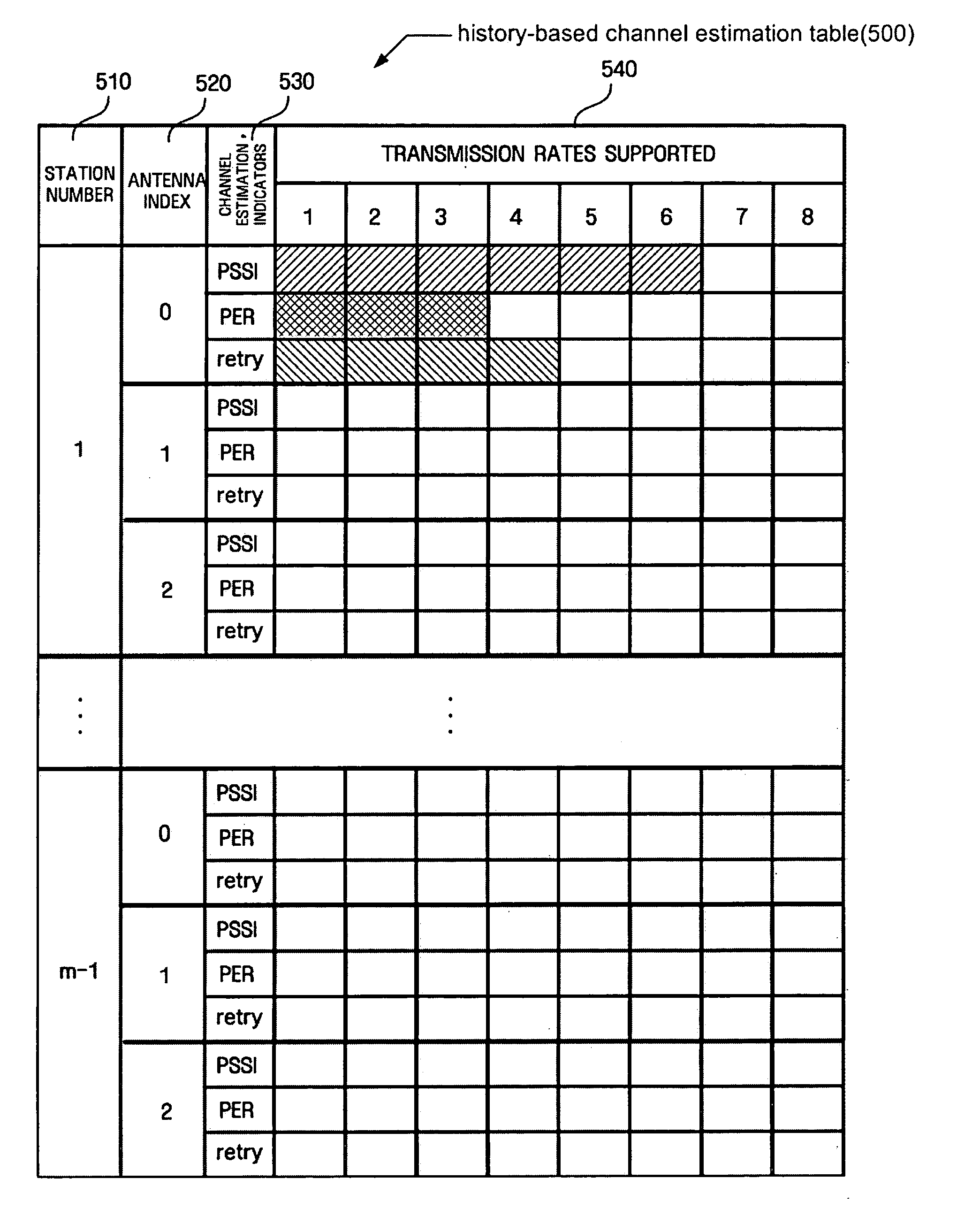
Provided is a link adaptation method for a multi input multi output (MIMO) system having a multi-antenna structure and a communicating method of MIMO stations in a basic service set (BSS), which constitutes a wireless communication network. The communicating method includes receiving the number of MIMO antennas and transmission rates supported by the respective MIMO antennas from a predetermined MIMO station, storing one or more channel estimation indicators obtained while receiving various frames from the predetermined MIMO station for each MIMO antenna and for each transmission rate supported by the MIMO antenna, determining threshold levels of the channel estimation indicators for each MIMO antenna, comparing threshold levels of channel estimation indicators for each MIMO antenna with an average of channel estimation indicators for each MIMO antenna, and determining a transmission rate based on comparison results to then transmit data to the predetermined MIMO station at the determined transmission rate.

Description

CROSS-REFERENCE TO RELATED APPLICATION [0001] This application claims the priority of Korean Patent Application No. 10-2004-0002969 filed on Jan. 15, 2004 in the Korean Intellectual Property Office, the disclosure of which is incorporated herein in its entirety by reference. BACKGROUND OF THE INVENTION [0002] 1. Field of the Invention [0003] The present invention relates to multiple input multiple output (MIMO) technology, and more particularly, to a link adaptation method suitable for a MIMO system having a multi-antenna structure. [0004] 2. Description of the Related Art [0005] In accordance with the proliferation and development of digital devices, digital technology has demanded a high-speed wireless local area network (LAN) system that will operate at data rates of 100 Mbits / sec or higher. To meet such demand, multiple input multiple output (MIMO) technology has been introduced as a candidate for one of the most promising technologies for speeding up next generation wireless LA...

Claims


Application Information

Patent Timeline
IPC IPC(8): G06F15/173H04B7/02H04B7/04H04B17/00H04L1/00H04L12/28H04L12/56
CPCH04B7/0413H04L1/0002H04L1/0025H04B17/318H04W48/08H04W84/12H04W28/22H04W28/10H04B7/02
Inventor KWON, CHANG-YEULYANG, CHIL-YOULKIM, TAE-KON
Owner SAMSUNG ELECTRONICS CO LTD
Learn More