Fuel reforming apparatus

a technology of fuel reforming apparatus and fuel mixture, which is applied in the direction of combustion air/fuel air treatment, machines/engines, gaseous fuels, etc., can solve the problems of difficult to allow the reforming reaction in the reforming reaction chamber to proceed, and the concentration of mixture flowing into the reforming reaction chamber becomes non-uniform, so as to achieve high reforming efficiency

Inactive Publication Date: 2005-07-28
TOYOTA JIDOSHA KK
View PDF5 Cites 4 Cited by
  • Summary
  • Abstract
  • Description
  • Claims
  • Application Information

AI Technical Summary

Benefits of technology

[0007] It is an object of the invention to provide a fuel reforming apparatus which allows fuel and gas containing oxygen to be mixed with each other uniformly, and which has high reforming efficiency.

Problems solved by technology

However, in the aforementioned fuel reforming apparatus, there is a possibility that the fuel and the air that are supplied into the mixing chamber are not mixed uniformly, and the concentration of the mixture that flows from the mixing chamber into the reforming reaction chamber becomes non-uniform.
Therefore, it is not easy to allow a reforming reaction in the reforming reaction chamber to proceed efficiently so as to obtain desired reforming efficiency.

Method used


Image

  • Fuel reforming apparatus
  • Fuel reforming apparatus
  • Fuel reforming apparatus

Examples


Embodiment Construction

[0017] Hereinafter, a preferred embodiment of the invention will be described with reference to the accompanying drawings.

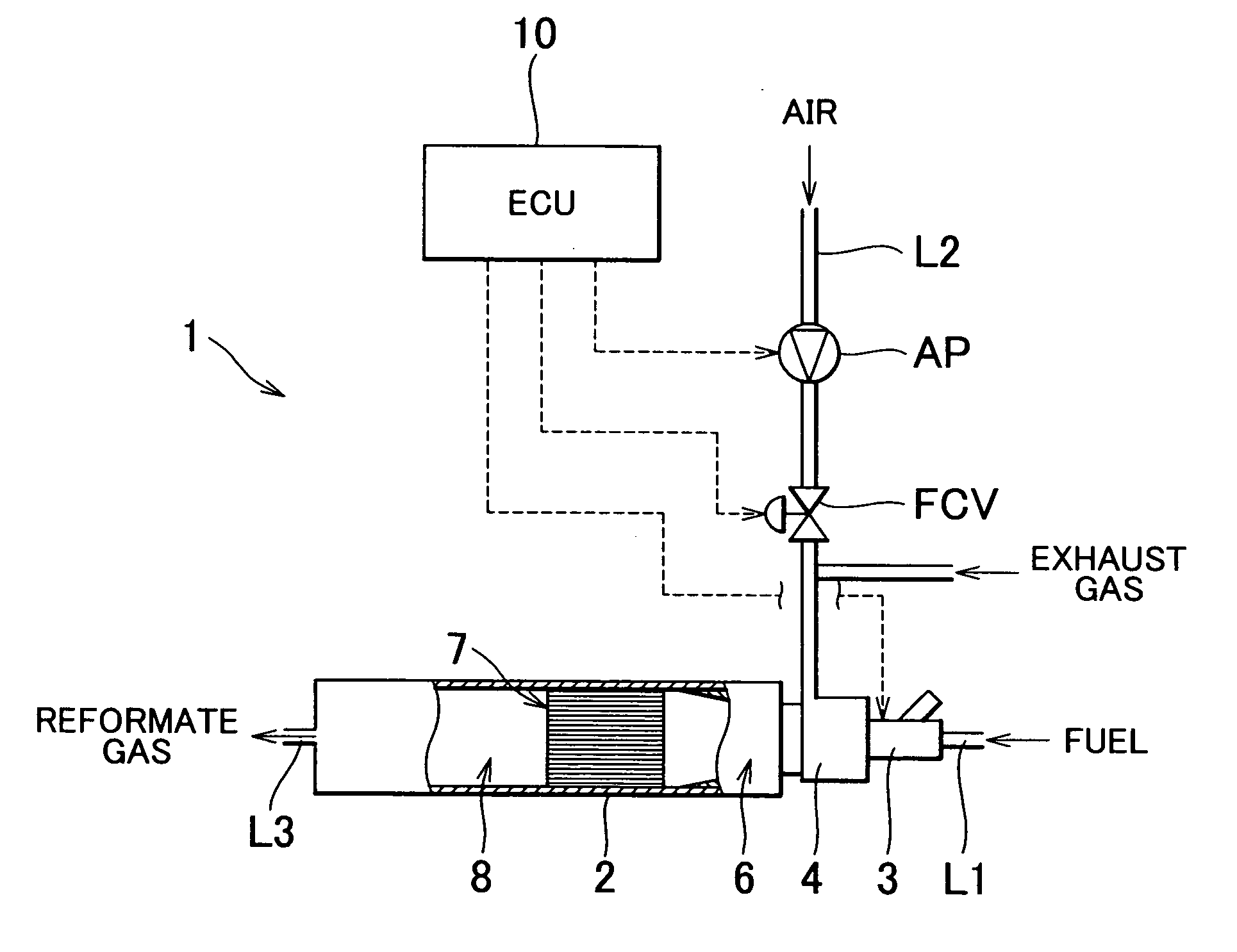
[0018]FIG. 1 is a schematic diagram showing a configuration of a fuel reforming apparatus according to an embodiment of the invention. A fuel reforming apparatus 1 shown in FIG. 1 can reform a mixture of air and hydrocarbon fuel such as gasoline. For example, the fuel reforming apparatus 1 is used for generating fuel (reformate gas) for an internal combustion engine that is a driving source of an automobile. As shown in FIG. 1, the fuel reforming apparatus 1 includes a main body 2 that is formed to have a generally cylindrical shape, and an injector (fuel supply means) 3 connected to an end portion of the main body 2 (an end portion on the right side in FIG. 1).

[0019] The injector 3 is connected to a fuel tank (not shown) via a fuel supply pipe L1 and a fuel pump (not shown). When the fuel reforming apparatus 1 is used, the injector 3 injects hydrocarbon fuel s...


PUM

PropertyMeasurementUnit
temperatureaaaaaaaaaa
areaaaaaaaaaaa
inner diameteraaaaaaaaaa

Abstract

A fuel reforming apparatus for reforming a mixture of fuel and gas containing oxygen includes an air-fuel mixing chamber into which fuel and air are supplied in such a manner that the fuel and the air are mixed with each other; a reforming reaction chamber which is provided downstream of the air-fuel mixing chamber, and which includes a reforming catalyst for reforming the mixture; and a mixture flow chamber which is provided between the air-fuel mixing chamber and the reforming reaction chamber. The cross sectional area of an outlet of the air-fuel mixing chamber is smaller than the cross sectional area of an inlet of the reforming reaction chamber. An inner wall surface of the mixture flow chamber is formed such that the outlet of the air-fuel mixing chamber is smoothly continuous with the inlet of the reforming reaction chamber.

Description

INCORPORATION BY REFERENCE [0001] The disclosure of Japanese Patent Application No. 2003-382992 filed on Nov. 12, 2003, including the specification, drawings, and abstract is incorporated herein by reference in its entirety. BACKGROUND OF THE INVENTION [0002] 1. Field of the Invention [0003] The invention relates to a fuel reforming apparatus for reforming a mixture of fuel and gas containing oxygen. [0004] 2. Description of the Related Art [0005] An internal combustion engine is known, in which a fuel reforming apparatus including a reforming catalyst is provided, and a fuel component obtained by reforming various types of fuel using the fuel reforming apparatus is burned in a combustion chamber, whereby stable combustion is obtained, and amounts of HC and NOx in exhaust gas are reduced (for example, refer to Japanese Patent Laid-Open Publication No. 2001-241365 (JP-A-2001-241365)). A typical fuel reforming apparatus that can be applied to such an internal combustion engine include...

Claims


Application Information

Patent Timeline
Patent Type & Authority Applications(United States)
IPC IPC(8): C01B3/38F02M25/07F02M27/02
CPCF02M25/0742Y02T10/121F02M27/02F02M26/36
Inventor WAKAO, KAZUHIROSAKURAI, KAZUHIROTAKEDA, KEISO
Owner TOYOTA JIDOSHA KK
Why Eureka
Try Eureka