Flash circulation smelting system constructed based on high-temperature heat exchanger

A high-temperature heat exchanger and heat exchanger technology, applied in waste heat treatment, energy efficiency improvement, lighting and heating equipment, etc., can solve problems such as large carbon emissions and unreasonable recycling of exhaust gas from the furnace, and achieve reforming efficiency High, fast reforming response speed, long-term stable working effect

Pending Publication Date: 2020-08-11
TIANJIN FLASH IRONMAKING TECH CO LTD
View PDF0 Cites 2 Cited by
  • Summary
  • Abstract
  • Description
  • Claims
  • Application Information

AI Technical Summary

Problems solved by technology

[0006] In view of this, the present invention aims to propose a flash cycle smelting system built on high-temperature heat exchangers to solve the problem that the exhaust gas from flash metallurgical equipment smelting oxidized ore has not been reasonably recycled and the carbon emission is large

Method used


Image

  • Flash circulation smelting system constructed based on high-temperature heat exchanger
  • Flash circulation smelting system constructed based on high-temperature heat exchanger
  • Flash circulation smelting system constructed based on high-temperature heat exchanger

Examples


Embodiment 1

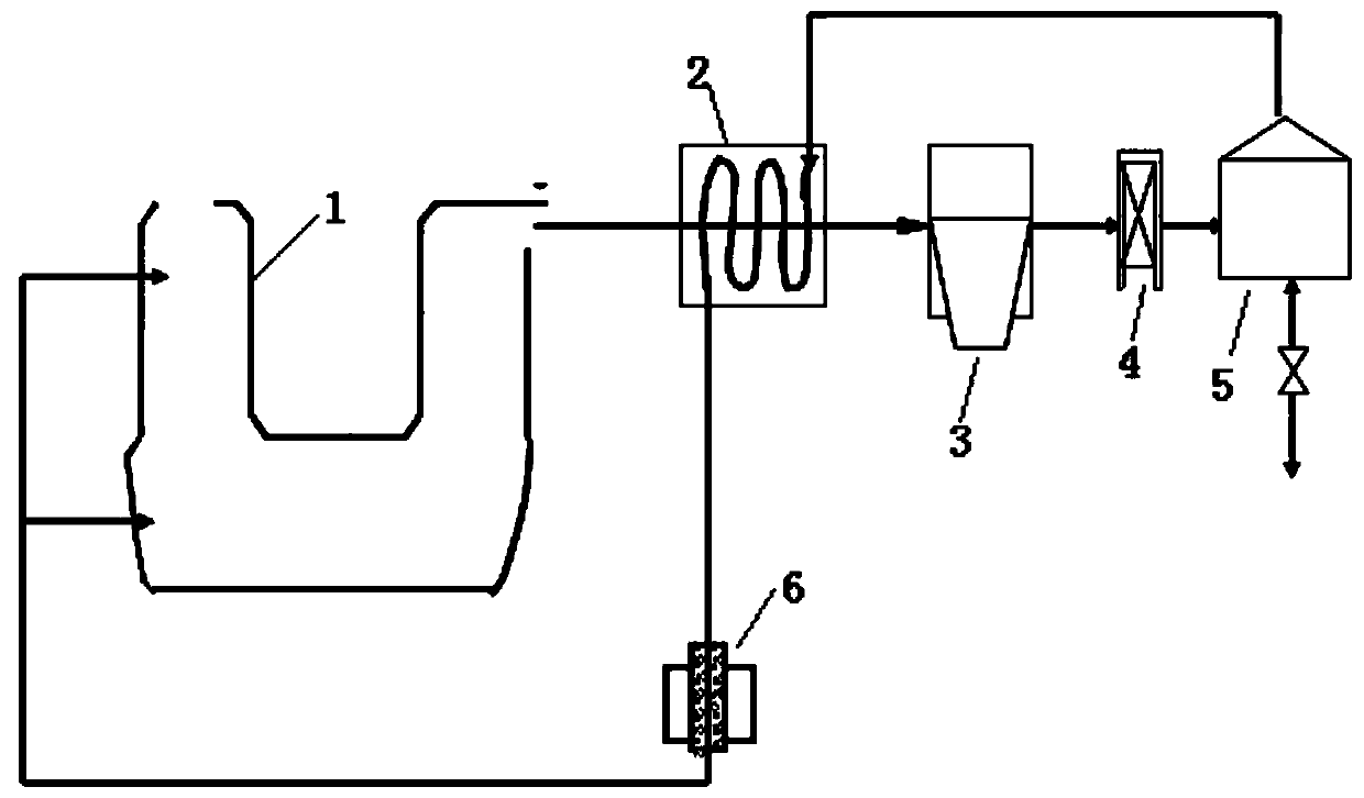
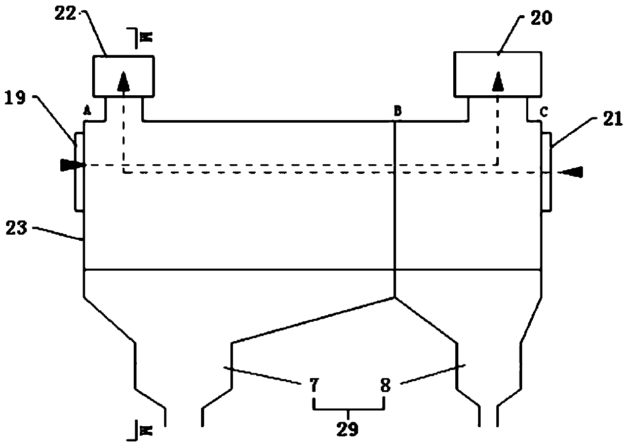
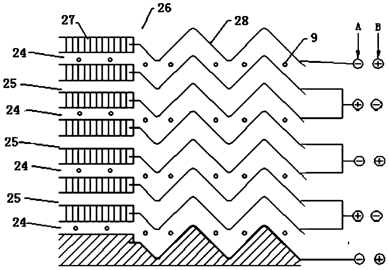
[0093] Such as figure 1 As shown, a flash cycle smelting system built on the basis of high-temperature heat exchangers includes a main gas pipeline. The main gas pipeline includes flash metallurgical equipment 1 connected in sequence through pipelines, heat medium flow channels of high-temperature heat exchanger 2, dust removal Desulfurization equipment 3, fan 4, gas storage and pressure regulating equipment 5, cold medium flow channel of high temperature heat exchanger 2, gas reforming equipment 6, reduced gas outlet of gas reforming equipment 6 and reducing gas inlet of flash metallurgy equipment 1 Connected through pipelines; wherein, the high-temperature heat exchanger 2 is a skylight heat exchanger, the heat medium flow channel of the high-temperature heat exchanger 2 is the hot flue gas channel 24 of the skylight heat exchanger, and the cold medium flow of the high-temperature heat exchanger 2 is The channel is the cold air channel 25 of the sky flash heat exchanger; the...

Embodiment 2

[0119] Such as Figure 8 As shown, on the basis of embodiment 1, different from embodiment 1 is that on the main gas pipeline, between the high temperature heat exchanger 2 and the dedusting and desulfurization equipment 3, an ore powder drying equipment 11 is provided, and the ore powder drying equipment 11 is used For dry mineral powder. The mineral powder drying equipment 11 is preferably a sky flash dryer.

[0120] Such as Figure 9 and 10 As shown, the Skyshine dryer includes an inner cylinder 12 and an outer cylinder 13 arranged coaxially and a rotary drive device that drives the rotation of the outer cylinder 13; Connection, the outer cylinder 13 and the sealing end 16 can be flexibly connected through a rotating bearing; there are many ways for the rotating drive device to drive the outer cylinder 13 to rotate, such as by setting gears on the outer wall of the outer cylinder 13, and by means of gear meshing. The motor drives the outer cylinder to rotate;

[0121] ...

Embodiment 3

[0137] Such as Figure 11 As shown, on the basis of Embodiment 1, the difference from Embodiment 1 is that a gas boiler 10 is provided between the dust removal and desulfurization equipment 3 and the fan 4 on the main gas pipeline. In practical applications, the position of the fan is relatively flexible. On the main gas main road, it can be installed between the dust removal and desulfurization equipment 3 and the gas boiler 10. As in this embodiment, it can also be installed between the gas boiler 10 and the gas storage and pressure regulating equipment. between 5. In addition, it should be noted that in this embodiment, a dehydration device or a gas-water separation device should be installed at the front end of the gas storage and pressure regulating device 5, which is used as a part of the gas storage and pressure regulating device 5 to dry the gas before storing it. .

[0138] The gas-fired boiler 10 is a thermal energy conversion device that uses the tail gas of the f...


PUM


Abstract

The invention provides a flash circulation smelting system constructed based on a high-temperature heat exchanger. The flash circulation smelting system comprises a coal gas main pipeline, the coal gas main pipeline comprises flash metallurgical equipment, a hot-medium flow pass of the high-temperature heat exchanger, dust-removal desulfurization equipment, a fan, gas-storage and pressure-regulating equipment, a cold-medium flow pass of the high-temperature heat exchanger and coal gas reforming equipment which communicate in sequence through pipelines, and a reduced coal gas outlet of the coalgas reforming equipment is connected with a reduced gas inlet of the flash metallurgical equipment through a pipeline. The flash circulation smelting system constructed based on the high-temperatureheat exchanger is a closed-loop system, and net-zero emission of carbon dioxide is achieved; and meanwhile heat energy and chemical energy of high-temperature discharged smoke of the flash metallurgical equipment are recycled, and comprehensive energy consumption of the system is lowered.

Description

technical field [0001] The invention belongs to the field of flue gas treatment in a flash smelting process, and in particular relates to a flash cycle smelting system built on the basis of a high-temperature heat exchanger. Background technique [0002] Flash metallurgy is traditionally only used in the smelting of metal sulfide ores, and is currently being applied to the smelting of metal oxide ores, such as iron ore, laterite nickel ore, etc. [0003] The basic principle of flash smelting of oxide ore is to convert high-temperature and high-concentration reducing gas (mainly containing CO and H 2 ), introducing a space specially used for reducing metal oxide ores to realize the gas phase reduction of metal oxides in a high-temperature space, and the products of space smelting fall into the molten pool, and the remaining metal oxides are reduced with carbon fixation in the molten pool. Since metal oxide ores usually contain FeO, in order to effectively reduce FeO, the eff...

Claims


Application Information

Patent Timeline
Patent Type & Authority Applications(China)
IPC IPC(8): C22B5/12F27D17/00C10K1/00
CPCC10K1/00C22B5/12F27D17/00Y02P10/25
Inventor 黄小兵夏明邱江波施小芳
Owner TIANJIN FLASH IRONMAKING TECH CO LTD
Why Eureka
Try Eureka