Sintering flue gas SCR denitration and vapor removal system and technology

A technology for sintering flue gas and denitrification, which is applied to the SCR denitration and dewhitening system and process field of sintering flue gas, can solve the problems of inability to meet environmental standards, low saturated flue gas temperature, atmospheric visual pollution, etc., and achieve good dust removal and dewhitening effects. , the effect of saving energy and low operating cost

Pending Publication Date: 2020-02-11
江苏朗润环保科技有限公司
View PDF6 Cites 7 Cited by
  • Summary
  • Abstract
  • Description
  • Claims
  • Application Information

AI Technical Summary

Problems solved by technology

At the same time, the temperature of the saturated flue gas after wet desulfurization is relatively low. If it is directly discharged from the chimney and mixed with the cold air outside, the water vapor in the flue gas will condense and form a white plume, which will cause more than just visual damage to the atmosphere. pollution, but actual pollution
However, the traditional flue gas denitrification treatment process is difficult to adapt to and cannot meet the new environmental standards, so it is essential for the denitrification transformation of the sintering section of the iron and steel industry

Method used


Image

  • Sintering flue gas SCR denitration and vapor removal system and technology
  • Sintering flue gas SCR denitration and vapor removal system and technology
  • Sintering flue gas SCR denitration and vapor removal system and technology

Examples


Embodiment Construction

[0057] The present invention will be further described in detail below in conjunction with the accompanying drawings and embodiments.

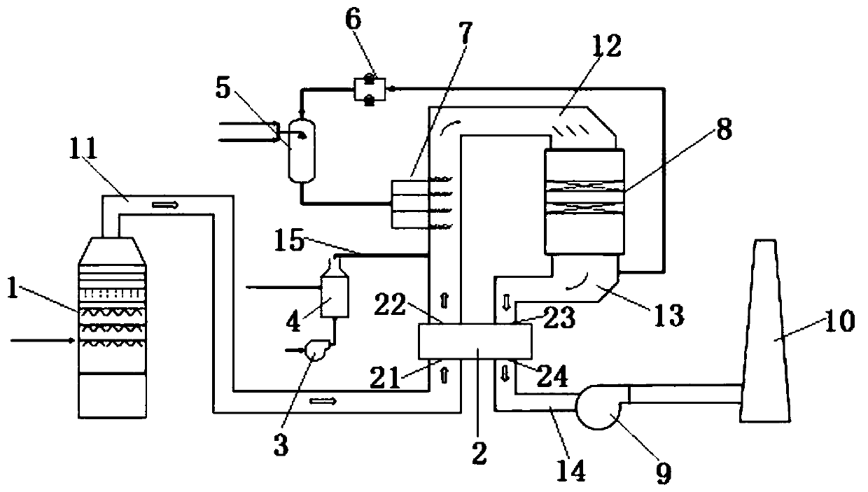
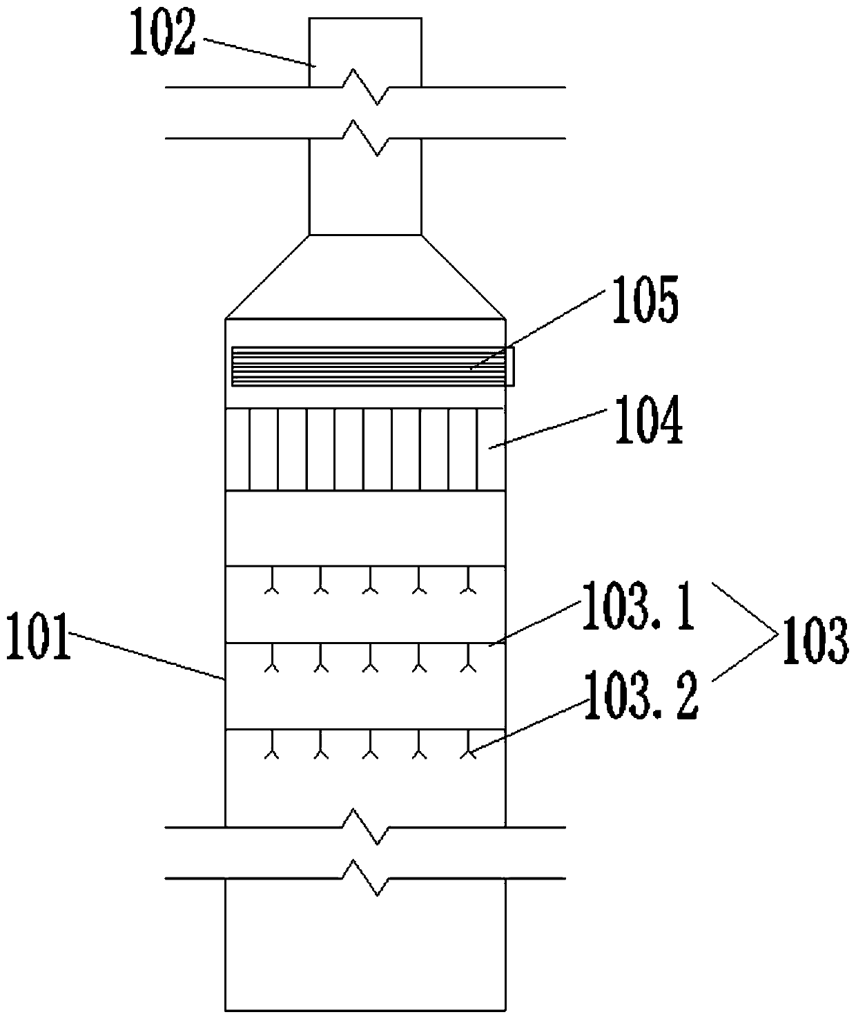
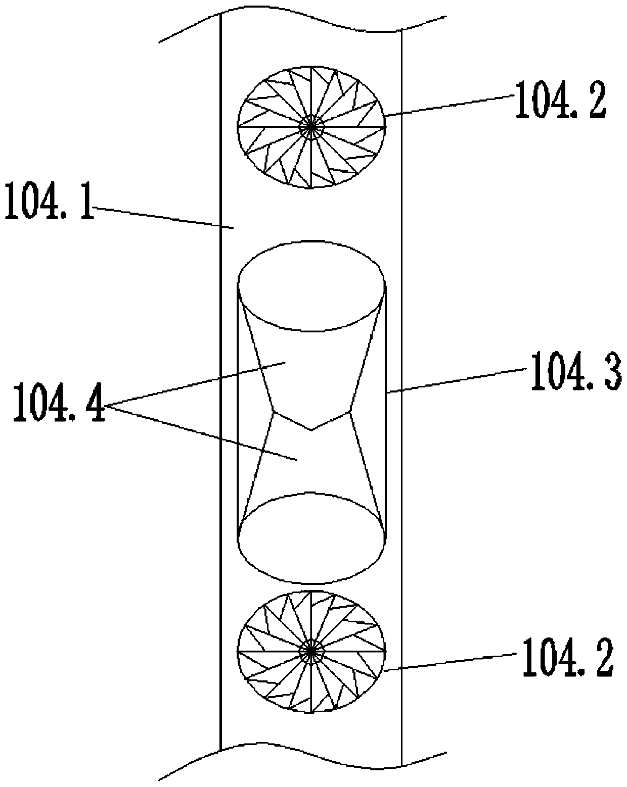
[0058] see Figure 1-Figure 4 , a sintering flue gas SCR denitrification and whitening system related to the present invention, comprising a flue gas condensation dewhitening demisting and dedusting tower 1, a heat exchange device 2, a hot blast stove 4, an ammonia water evaporator 5, a dilution fan 6, and an ammonia spraying grid 7. The SCR denitrification reaction device 8 and the smoke exhaust device 10, the first main flue 11 is connected between the raw flue gas inlet 21 at the lower part of the heat exchange device 2 and the gas outlet of the flue gas condensation, whitening, fogging and dust removal tower 1 , the second main flue 12 is connected between the original flue gas outlet 22 on the upper part of the heat exchange device 2 and the air inlet of the SCR denitrification reaction device 8, and the clean flue gas inlet 23 on the upp...


PUM


Abstract

The invention relates to a sintering flue gas SCR denitration and vapor removal system. The system comprises a flue gas condensation vapor-removal defogging dedusting tower, a heat exchange device, ahot-blast stove, an ammonium hydroxide evaporator, a dilution fan, an ammonia injection grid, an SCR denitration reaction device and a flue gas exhaust device. The heat exchange device is arranged between the flue gas condensation vapor-removal defogging dedusting tower and the SCR denitration reaction device. The heat exchange device is used for heat exchange on flue gas to be denitrated or denitrated flue gas to change the temperature, an original flue gas outlet of the heat exchange device is connected with a gas inlet of the SCR denitration reaction device through a second main flue, the hot-blast stove and the ammonia injection grid are arranged in sequence in the flowing direction of the flue gas in the second main flue, and the ammonium hydroxide evaporator and the dilution fan arearranged between the ammonia injection grid and a gas outlet of the SCR denitration reaction device. The sintering flue gas SCR denitration and vapor removal system can carry out SCR denitration on desulfurated sintering flue gas while carrying out vapor removal treatment, the effect of purifying sintering flue gas desulfurated with a wet method is improved, and environmental pollution is reduced.

Description

technical field [0001] The invention belongs to the field of sintering flue gas pollutants and flue gas dewhitening control, and in particular relates to a sintering flue gas SCR denitrification and whitening system and process. Background technique [0002] At present, the iron and steel smelting industry is an industry with high energy consumption and heavy pollution. The sintering flue gas produced by the high-temperature sintering process of iron and steel contains a variety of pollutant gases, including particulate matter, NOx and SO2 and other acid gases, and these pollutant gases are one of the main culprits of air pollution. The current "Steel Sintering and Pelletizing Industry Air Pollutant Emission Standard" (GB28662-2012) stipulates that the emission limits of particulate matter, NOx and SO2 in the sintering flue gas are 50mg / m 3 , 200mg / m 3 、300mg / m 3 . However, at present, the control of sintering flue gas is still mainly in the aspects of desulfurization an...

Claims


Application Information

Patent Timeline
Patent Type & Authority Applications(China)
IPC IPC(8): B01D50/00B01D53/86B01D53/56
CPCB01D53/8625B01D2258/0283B01D2251/2062B01D50/40
Inventor 沈凯李博
Owner 江苏朗润环保科技有限公司
Why Eureka
Try Eureka